Simple electronic recorder
At first there was an idea
At work (I work in medicine) two electromechanical recorders are puffing and suffering, and I, along with them: mascara, mechanics - whether you know it's unpleasant. One day, the idea came to my head: why not replace the two recorders choking with old age with a simple data collection system consisting of an ADC controller and a PC (even if weak and old) with the appropriate software with output capability to a printer? And then it started in my head and spun ...
Lyrics
Since, apart from the idea, I had nothing: neither experience, nor special knowledge in circuit engineering and electronics, I had to shovel a fair amount of literature and search the open spaces of the network. Also, the project was supposed to be a budget one, and therefore I had to master the LUT method, learn how to etch the boards, drill and solder - I don’t regret it at all. Thus, I walked some, albeit small, path — a path of trial and error; I cite some observations made by me in the process; maybe someone will compare them with his own and agree, or he may not agree:
- a quick start like this will not work, you should not build illusions - you will have to sweat;
- it is better not to use emulators like Proteus at first, it is much more useful to experiment on real hardware, touch your hands, taste it and taste it. For the simplest debugging, UART is sufficient;
- circuit boards - brr, I prefer LUT + ferric chloride + drilling, it turns out a little longer, but it gives a clear understanding of what you are doing;
- I advise you not to get involved in the installation of smd cases and the “minimization” of circuit boards - it is quite difficult for a beginner, sometimes it is easier to reconnect the board in an “increased scale” with a simple mounted installation (again, more useful for understanding).
About ADC theory and first attempt
After some research it turned out that it is possible to implement the conceived idea in several ways. The simplest solutions are given in the Patrick Gell book (see the basement), the basics of analog-digital signal conversion are also explained there. I give a typical scheme taken from there:
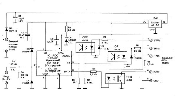
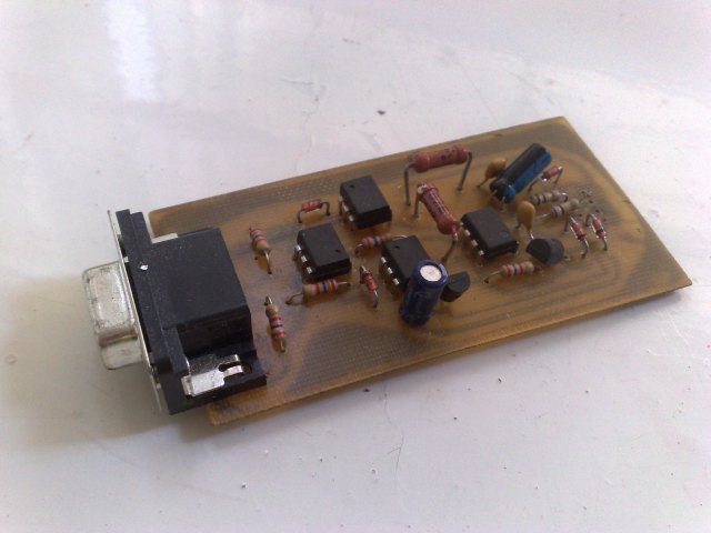
The circuit is based on the ADC chip. The interaction with the PC is realized at the software level by forming control pulse sequences on the modem lines of the RS-232 interface of the PC. This circumstance limits the data transfer rate and increases the likelihood of transmission error. The measurement accuracy is determined by the ADC digit capacity (8 bits in this case), the accuracy of the reference voltage supplied to the ADC (the LT 1009 CZ ion is used here). The speed of signal digitization depends on the time of ADC conversion and, again, on the accuracy of the interface organization by the developer. Actually, this implementation was my first combat experience (see photo below), but soon I was disappointed because I felt the need for a more elegant solution. The control program (driver) was written under DOS on pascal.
Such schemes, despite their viability, in view of these shortcomings are practically not used, ADC chips are usually used together with a microcontroller, which already organizes data transfer at the hardware level, simultaneously performing any control operations or primitive data processing. A good example of such a solution is such an AVR microcontroller based circuit:
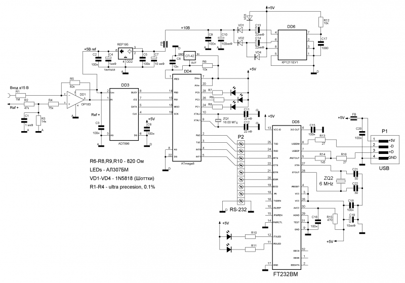
The circuit is based on Atmega8 microcontroller, FT232BM USB interface chip, AD7876 ADC chip, and REF195GP ION. At the input, a differentiator based on an operational amplifier drives the input signal to the range of 0-5V (reference voltage of the ADC). Analog-to-digital conversion of the signal is performed by the AD7876 ADC microcircuit and transmits data via the SPI interface to the microcontroller, which, in turn, “throws” the result into the usb-port via the UART and the FT232BM interconnect chip.
As part of my task, I need to use 4 ADC channels. An attractive possibility is the use of a built-in ADC microcontroller with a switched input, which will make it possible to abandon the use of an external ADC microcircuit and provide the necessary number of channels - a cheap and simple solution. It is not necessary to include a differentiator in the circuit, since the amplitude of the signal at each of the inputs does not exceed 2-2.5 V.
')
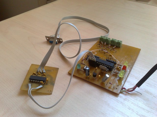
The scheme of my device
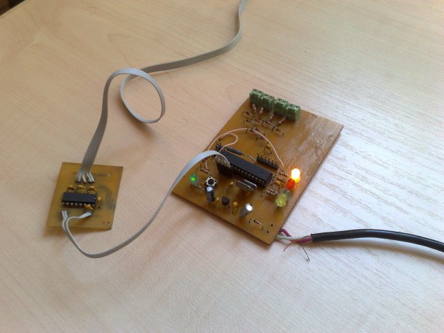
The ADC controller is based on the AVR Atmega8 microcontroller. MK has a sufficient number of legs in order to connect 4 ADC channels, signal LEDs, PC interface board. The circuit uses an external ION L1009CZ. The interface board with the PC through the RS-232 interface is based on the MAX232 chip and is separated from the main module, if necessary, can be replaced with a board with an FT232 on board for pairing via USB, or with any bluetooth module (type BTM-222 , HC-04 ) for communication via blootooth interface. The figure below shows a schematic diagram of the device being developed:

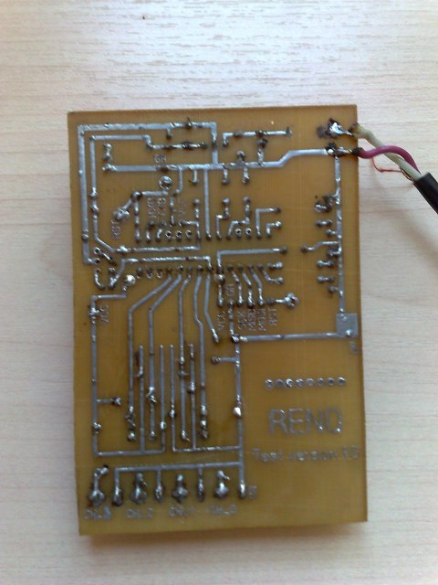
The power scheme is standard - based on the 78L05 linear stabilizer, the HL1 signaling LED is present. The schematic diagram is drawn using sPlan, the layout of the board is in Sprint Layout. At the end of the technological chain - LUT + etching + drilling + soldering we get:
Bottom view:
Software part
For coding I used AVRStudio + WinAVR (AVR-GCC) under Windows, an alternative for Linux - Eclipse + AVR-GCC. I tried CodeVisionAVR - not bad for a start, it has a built-in code generator, a code limit of 2 KB.
The firmware works according to the following algorithm:
- initialization: functions - UART_init, ADC_init, LED_init;
- sequential interrogation of channels in an infinite interrupt cycle and data transfer via UART to the PC com port.
In order to debug the text test messages are distributed. Switching the polling channel is highlighted by the corresponding LED. During initialization, all 4 LEDs flash simultaneously. In order to switch the LEDs was noticeable to the eye deliberately put a delay.
/* WinAVR version... Chip: ATmega8 Memory Model: SMALL Data Stack Size: 256 bytes Clock frequency: 4.0000 MHz PCO - PC3 - Channels */ // ATmega8 I/O register definitions #include <avr/io.h> #include <util/delay.h> #include <avr/interrupt.h> #include <stdio.h> #define ADC_VREF_TYPE 0x40 #define ADC_CH1_MUX 0x1 #define ADC_CH2_MUX 0x2 #define ADC_CH3_MUX 0x3 // Counter of channel's changes uint8_t i = 0; void LED_init(void){ printf("Led initialization....\r\n"); char j = 0; DDRD|= (1<<DDD7); DDRB|= ((1<<DDB0)|(1<<DDB1)|(1<<DDB2)); for(j=0;j<5;j++) { PORTD|=(1<<PD7); PORTB|=(1<<PB0)|(1<<PB1)|(1<<PB2); _delay_ms(600); PORTB&= ~((1<<PB0)|(1<<PB1)|(1<<PB2)); PORTD&= ~(1<<PD7); _delay_ms(600); } } //Sending of single char static int my_putchar(char c, FILE *stream){ while((UCSRA&(1<<UDRE)) == 0); UDR = c; return 0; } void myUART_init(void){ // USART initialization // Communication Parameters: 8 Data, 1 Stop, No Parity // USART Receiver: Off // USART Transmitter: On // USART Mode: Asynchronous // USART Baud rate: 9600 UCSRA=0x00; UCSRB=0x08; UCSRC=0x86; UBRRH=0x00; UBRRL=0x19; //Redirection of stdout static FILE mystdout = FDEV_SETUP_STREAM(my_putchar, NULL, _FDEV_SETUP_WRITE); stdout = &mystdout; printf("UART initialization....\r\n"); } void ADC_init(void){ // ADC initialization // ADC Voltage Reference: AREF pin // ADC High Speed Mode: Off // ADC Auto Trigger Source: None // Select ADC input 0 printf("ADC initialization....\r\n"); ADMUX=ADC_VREF_TYPE; ADCSRA=0x8E; } // ADC interrupt service routine ISR(ADC_vect){ // Here is sending data in RS-232 printf("I'am in interrupt...\r\n"); uint16_t data = ADCL; data+= (ADCH<<8); printf("Ch_%u=%u\r\n",i,data); //Control of ADMUX's state uint8_t pr = ADMUX; printf("ADMUX = %u\r\n",pr); data = 0; if (i == 3) { i = 0; ADMUX&= ~ADC_CH3_MUX; PORTB&= ~(1<<PB2); PORTD|=(1<<PD7); //Change of channel data = ADMUX; printf("3to0,ADMUX = %u\r\n",data); data=0; _delay_ms(25); } else { if (i == 0) { ADMUX|= ADC_CH1_MUX; PORTD&= ~(1<<PD7); PORTB|= (1<<PB0); //Change of channel data = ADMUX; printf("0to1,ADMUX = %u\r\n",data); data=0; } if (i == 1) { ADMUX&= ~ADC_CH1_MUX; ADMUX|= ADC_CH2_MUX; PORTB&= ~(1<<PB0); PORTB|= (1<<PB1); //Change of channel data = ADMUX; printf("1to2,ADMUX = %u\r\n",data); data=0; } if (i == 2) { ADMUX&= ~ADC_CH2_MUX; ADMUX|= ADC_CH3_MUX; PORTB&= ~(1<<PB1); PORTB|= (1<<PB2); //Change of channel data = ADMUX; printf("2to3,ADMUX = %u\r\n",data); data=0; } i++; _delay_ms(25); } // Start a new AD conversion ADCSRA|=0x40; }; int main(void) { myUART_init(); ADC_init(); LED_init(); printf("I'am in main...\r\n"); // Global enable interrupts sei(); // Start the first AD conversion ADCSRA|=0x40; while (1); } After debugging is complete, test messages need to be commented out and unnecessary delays removed. The code was written buried in datasheet , everything is written in detail.
Programmer
The simplest programmer STK200 was used for the firmware, and the wiring of the board had to be done on its own in order to facilitate the soldering. Stitched avrdude. I tried avreal - an excellent alternative, there were no difficulties either.


Finally - it works!
After debugging the code, several erase / write cycles of the MK device came to life and blinked the LEDs to my great joy.
On the PC, used a text terminal to work with the COM port. They are in bulk in the network, if you wish, you can write yourself, for example, using QT + QSerialDevice (a wonderful library for working with com ports, written by our compatriot Denis Shienkov), or whatever.
Finally
The plans left only writing software for the PC. Actually, I'm already writing, using QT + QSerialDevice + QWT in conjunction, and soon, soon, I feel my graphics will crawl across the display. And still thinking about how to implement the hardware on the MK STM32F series, taking as a basis the STM32VLDISCOVERY mentioned already on the Habré — I want to master the new hardware.
Useful literature
Will help digest all the above books:
P. Horowitz, W. Hill. “The Art of Circuit Engineering” is a classic thing;
Patrick Gell. How to turn a personal computer into a measuring complex is mentioned above.
Source: https://habr.com/ru/post/125907/
All Articles