FPGA clock with Quartus II and some Verilog
In this topic I want to talk about how to FPGA you can implement the clock. Someone may find this strange, unnecessary - but one has to start somewhere, so this topic will be useful for beginners who have blinked with LEDs and want something more interesting.
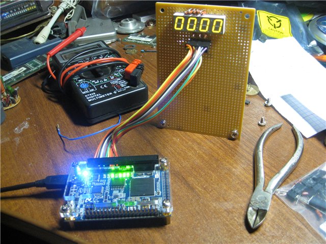
It means that we have:
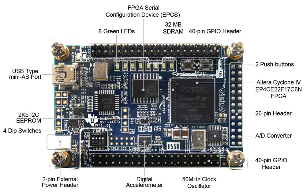
1) Terasic DE0-Nano debug board with Cyclone IV on board.
2) A model with a seven-segment indicator soldered on it, to which we will output hours and minutes /
For these two points, complete freedom of choice almost any FPGA will do, and even one will do the layout with the indicator as it does.
Now about the project.
We will go in order. First of all, let us ask ourselves: what is a watch? A clock is a device that counts time. In order to count it, we need an exact source. Our board has a 50 MHz clock signal generator. Too much, so we need to divide it by 50,000,000 to get a frequency of 1 Hz (one “tick” per second). How to share? I did it in two stages: using PLL, divided by 50 and using a counter, divided by a million.
What is a PLL? Roughly speaking, this is such a thing that can change the clock signal: multiply, divide, shift in phase, change the duty cycle. Cyclone IV has 4 of them, so why not use one ...
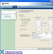
To do this, open the MegaWizard Plugin Manager and use ALT_PLL from the IO section:
1) Set the input frequency to 50 MHz:
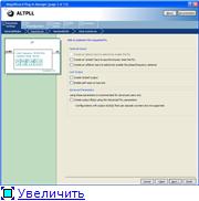
2) Disable unnecessary inputs:
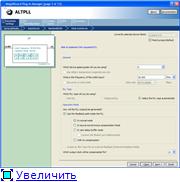
3) Click Next three times and get into the window of signal parameters selection, where we set the division factor to 50:
Then you can safely click Finish, save and paste into the project.
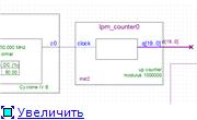
This is the beauty we received:

')
On the left is the input 50 MHz, on the right 1 MHz.
Now we need to divide by another million - for this we use the counter modulo 1000000. The counting module is the number of possible states of the counter.
We create it using the same MegaWizard using LPM_Counter.
Set the bit depth - 20 bits, and choose modulus, with a count modulus of 1,000,000.
We get this:
Now we have neat 1 Hz, which can be obtained from the senior (19) level.
Next, we need to implement a cascade of 3 meters: two modulo 60 (minutes and seconds), and one modulo 24 (obviously, a clock).
The second counter - with asynchronous reset, which occurs when you press any button (setting hours / minutes):
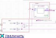
As you can see, the Carry Out output is used (transfer in case of overflow to the next counter), and seconds are displayed on the LEDs.
The following 2 counters are constructed in the same way, with one exception: to set the time, it is necessary to send a clock signal faster than 1 Hz, in order not to fall asleep when setting up. :)
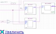
For this we use button-controlled multiplexers:

The upper multiplexer is used to select which frequency to feed to the counter, and the lower one chooses what to input to cin: transfer from the cout second counter, or just the log level. "one".
The essence of the cin input is that the meter counts only if there is a logical unit level at this input. That is, when the seconds counter overflows, it raises the cout to one. This “1” is fed to the cin input of the next counter and it reports one minute, and so on.
Thus, when the key [0] button is released, the minute counter counts 1 time per minute (which is logical), and when it is pressed, it counts about 4 times per second.
Similarly for an hour counter:
The upper multiplexer controls the transfer, and the lower frequency, with the exception of one moment: when the key [0] button is pressed, the clock signals do not arrive at the meter's water (this is done so that the clock does not get lost when setting the minutes). This is done by the AND element, to the input of which a clock signal and key [0] are supplied. When the button is released, the key [0] is high and q [19] passes through it, while the button is pressed, the level is “0” and the output is also “0”. In principle, it would be possible to enable the “count enable” input at the counter and disable the counter through it — in this task it is not fundamental.
Now we need to display data from the counters. To do this, we need to make a binary to decimal converter. This is a representation of the decimal number in binary code, when each decimal digit is given in separate 4 binary digits.
Example:
738 = 0111 0011 1000.
For this conversion, we use the double-dabble algorithm.
The essence of the algorithm:
1) Move the binary number to the left by one digit.
2) If 4 shifts - the number of BCD in the columns "tens" and "units". End of algorithm
3) If the number in any column is greater than 4, add 3.
Go to P1.
Here is an illustration:

And here is what we need to implement in order for this conversion to be done without delays:
s16.radikal.ru/i191/1107/a4/59618e3101ca.png
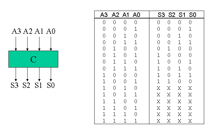
Each module C adds 3 to the input, if the input number is greater than 4.
Here he himself and the truth of his work:
To implement this whole economy, we write here two such modules on verilog:
Save and paste into the project in the amount of two pieces:

One will be for hours, the other for minutes.
Now it is necessary to make a lyrical digression regarding our indicator.
I used Lite-On ltc-4727js.
According to the datasheet, it has segments with a common cathode for each digit + inputs of the anodes of the segments of each digit combined. This means that we can light only 1 digit at a time. It does not matter, we will light them in turn, only we will switch very quickly. So fast that even Chuck Norris will not notice a flicker ;-)
The most interesting parts of the datasheet:

and

How did I connect all this?
But using these pins:

With the segments, I think, everything is clear, but what is the mysterious digit [4..0] ... Everything is simple - digit [4..1] -
these are our digits, and the digit [0] is an auxiliary segment (a colon between 2 and 3 digits). I will tell you, the most difficult thing is to correctly connect everything and correctly set the correspondence between the FPGA outputs and our pines!
Let us now analyze the output mechanism on the indicator.
This is such a monstrous design:

On the left we have bin-to-BCD converters. In the center of attention - a multiplexer for 5 inputs with a width of 4 bits. The first 4 inputs are digits, the fifth input is for igniting points (which flash once a second). Below you can see the scheme, which for this second entry serves 1111 or 1110. About why this is so - a little further. Depending on what combination comes to the control input of the multiplexer, it outputs the necessary digit to the decoder (the device of which we will consider a little later). Above it is a device that chooses which cathode to apply “0” to light up the desired segment. Here are his insides:
Pay attention to the record type 5'b0zzzz. Here 5'b means that we set 5 bits in binary form, 0 - zero level, z - high-resistance state (current does not flow to pin). And why exactly 0? Yes, because we have a common cathode on the figure, the current flows from the anode to the cathode, or from 1 to 0. So we set 0 on the cathode, and 1 on the anode.
Now the device decoder:
assign {segA, segB, segC, segD, segE, segF, segG, segDP} = SevenSeg;
endmodule
Here, depending on what number we need, it is chosen which segments to light.
Two points of interest are the default and the number 1111. When our BCD accepts a value different from the given (1110, which was mentioned earlier), then all segments are turned off. When 1111 arrives here, segments A and B are lit. As you can see from the datasheet, they are also connected to points L1 and L2.
That's all.
We put everything together inone pile , assign pins, compile (yeah, use less than 1% of our mighty pebble) and fill it into FPGA.
Here is the project:
ifolder.ru/24865983
It is necessary to choose your FPGA, and reassign pins. True, I used PLL ... Therefore, when transferring a project to another FPGA, you will need your input frequency (not a fact that you will have 50 MHz there) to divide it yourself.
Here's a video:
www.youtube.com/watch?v=iUoiOO8wYls
Sources:
1) Date on the indicator:
pdf.eicom.ru/datasheets/lite-on_pdfs/ltc-4727js/ltc-4727js.pdf
2) Transfer from BIN to BCD:
www.johnloomis.org/ece314/notes/devices/binary_to_BCD/bin_to_bcd.html
www.ece.msstate.edu/courses/ece4743/fall2007/Shift_add_3.pdf
3) Segment output:
www2.engr.arizona.edu/~rlysecky/courses/ece274-07f/labs/lab4.pdf
we.easyelectronics.ru/Shematech/dinamicheskaya-indikaciya_2.html
www.fpga4fun.com/Opto4.html
4) Decryptor:
www.fpga4fun.com/Opto3.html
Thank you for your attention, I hope someone will come in handy!
UPD
Thanks for the comments everyone!
I do not know how it turned out in this blog. I wanted to cut, fill in the pictures of the norms, remake something ... But today I didn’t go to Habr at all!
There is an idea to get time from outside, for example, via NTP.
About hosting - I was advised in a personal, poured there.
This is my first topic, there were no publications prior to this experience, I uploaded the pictures to the first remembered hosting.
I just happened to be in my hometown and with normal internet. Tomorrow I will take into account the wishes!
It means that we have:
1) Terasic DE0-Nano debug board with Cyclone IV on board.
2) A model with a seven-segment indicator soldered on it, to which we will output hours and minutes /
For these two points, complete freedom of choice almost any FPGA will do, and even one will do the layout with the indicator as it does.
Now about the project.
We will go in order. First of all, let us ask ourselves: what is a watch? A clock is a device that counts time. In order to count it, we need an exact source. Our board has a 50 MHz clock signal generator. Too much, so we need to divide it by 50,000,000 to get a frequency of 1 Hz (one “tick” per second). How to share? I did it in two stages: using PLL, divided by 50 and using a counter, divided by a million.
What is a PLL? Roughly speaking, this is such a thing that can change the clock signal: multiply, divide, shift in phase, change the duty cycle. Cyclone IV has 4 of them, so why not use one ...
To do this, open the MegaWizard Plugin Manager and use ALT_PLL from the IO section:
1) Set the input frequency to 50 MHz:

2) Disable unnecessary inputs:

3) Click Next three times and get into the window of signal parameters selection, where we set the division factor to 50:

Then you can safely click Finish, save and paste into the project.
This is the beauty we received:

')
On the left is the input 50 MHz, on the right 1 MHz.
Now we need to divide by another million - for this we use the counter modulo 1000000. The counting module is the number of possible states of the counter.
We create it using the same MegaWizard using LPM_Counter.
Set the bit depth - 20 bits, and choose modulus, with a count modulus of 1,000,000.
We get this:

Now we have neat 1 Hz, which can be obtained from the senior (19) level.
Next, we need to implement a cascade of 3 meters: two modulo 60 (minutes and seconds), and one modulo 24 (obviously, a clock).
The second counter - with asynchronous reset, which occurs when you press any button (setting hours / minutes):

As you can see, the Carry Out output is used (transfer in case of overflow to the next counter), and seconds are displayed on the LEDs.
The following 2 counters are constructed in the same way, with one exception: to set the time, it is necessary to send a clock signal faster than 1 Hz, in order not to fall asleep when setting up. :)
For this we use button-controlled multiplexers:

The upper multiplexer is used to select which frequency to feed to the counter, and the lower one chooses what to input to cin: transfer from the cout second counter, or just the log level. "one".
The essence of the cin input is that the meter counts only if there is a logical unit level at this input. That is, when the seconds counter overflows, it raises the cout to one. This “1” is fed to the cin input of the next counter and it reports one minute, and so on.
Thus, when the key [0] button is released, the minute counter counts 1 time per minute (which is logical), and when it is pressed, it counts about 4 times per second.
Similarly for an hour counter:

The upper multiplexer controls the transfer, and the lower frequency, with the exception of one moment: when the key [0] button is pressed, the clock signals do not arrive at the meter's water (this is done so that the clock does not get lost when setting the minutes). This is done by the AND element, to the input of which a clock signal and key [0] are supplied. When the button is released, the key [0] is high and q [19] passes through it, while the button is pressed, the level is “0” and the output is also “0”. In principle, it would be possible to enable the “count enable” input at the counter and disable the counter through it — in this task it is not fundamental.
Now we need to display data from the counters. To do this, we need to make a binary to decimal converter. This is a representation of the decimal number in binary code, when each decimal digit is given in separate 4 binary digits.
Example:
738 = 0111 0011 1000.
For this conversion, we use the double-dabble algorithm.
The essence of the algorithm:
1) Move the binary number to the left by one digit.
2) If 4 shifts - the number of BCD in the columns "tens" and "units". End of algorithm
3) If the number in any column is greater than 4, add 3.
Go to P1.
Here is an illustration:
And here is what we need to implement in order for this conversion to be done without delays:
s16.radikal.ru/i191/1107/a4/59618e3101ca.png
Each module C adds 3 to the input, if the input number is greater than 4.
Here he himself and the truth of his work:
To implement this whole economy, we write here two such modules on verilog:
module add3(in,out);
input [3:0] in;
output [3:0] out;
reg [3:0] out;

always @ (in)
case (in)
4'b0000: out <= 4'b0000;
4'b0001: out <= 4'b0001;
4'b0010: out <= 4'b0010;
4'b0011: out <= 4'b0011;
4'b0100: out <= 4'b0100;
4'b0101: out <= 4'b1000;
4'b0110: out <= 4'b1001;
4'b0111: out <= 4'b1010;
4'b1000: out <= 4'b1011;
4'b1001: out <= 4'b1100;
default: out <= 4'b0000;
endcase
endmodule

module binary_to_BCD(A,ONES,TENS);
input [5:0] A;
output [3:0] ONES, TENS;

wire [3:0] c1,c2,c3;
wire [3:0] d1,d2,d3;

assign d1 = {1'b0,A[5:3]};
assign d2 = {c1[2:0],A[2]};
assign d3 = {c2[2:0],A[1]};
add3 m1(d1,c1);
add3 m2(d2,c2);
add3 m3(d3,c3);
assign ONES = {c3[2:0],A[0]};
assign TENS = {1'b0,c1[3],c2[3],c3[3]};
endmodule
Save and paste into the project in the amount of two pieces:
One will be for hours, the other for minutes.
Now it is necessary to make a lyrical digression regarding our indicator.
I used Lite-On ltc-4727js.
According to the datasheet, it has segments with a common cathode for each digit + inputs of the anodes of the segments of each digit combined. This means that we can light only 1 digit at a time. It does not matter, we will light them in turn, only we will switch very quickly. So fast that even Chuck Norris will not notice a flicker ;-)
The most interesting parts of the datasheet:
and

How did I connect all this?
But using these pins:

With the segments, I think, everything is clear, but what is the mysterious digit [4..0] ... Everything is simple - digit [4..1] -
these are our digits, and the digit [0] is an auxiliary segment (a colon between 2 and 3 digits). I will tell you, the most difficult thing is to correctly connect everything and correctly set the correspondence between the FPGA outputs and our pines!
Let us now analyze the output mechanism on the indicator.
This is such a monstrous design:

On the left we have bin-to-BCD converters. In the center of attention - a multiplexer for 5 inputs with a width of 4 bits. The first 4 inputs are digits, the fifth input is for igniting points (which flash once a second). Below you can see the scheme, which for this second entry serves 1111 or 1110. About why this is so - a little further. Depending on what combination comes to the control input of the multiplexer, it outputs the necessary digit to the decoder (the device of which we will consider a little later). Above it is a device that chooses which cathode to apply “0” to light up the desired segment. Here are his insides:
module segment_select (in,out,sel);
input in;
output reg [4:0] out;
output reg [2:0] sel;

always @ (posedge in)
if (sel == 4)
sel = 0;
else sel = sel + 1;

always @(*)
case (sel)
0: out <= 5'b0zzzz;
1: out <= 5'bz0zzz;
2: out <= 5'bzz0zz;
3: out <= 5'bzzz0z;
4: out <= 5'bzzzz0;
default: out <= 5'bzzzzz;
endcase
endmodule
Pay attention to the record type 5'b0zzzz. Here 5'b means that we set 5 bits in binary form, 0 - zero level, z - high-resistance state (current does not flow to pin). And why exactly 0? Yes, because we have a common cathode on the figure, the current flows from the anode to the cathode, or from 1 to 0. So we set 0 on the cathode, and 1 on the anode.
Now the device decoder:
module decoder_7seg (BCD, segA, segB, segC, segD, segE, segF, segG, segDP);

input [3:0] BCD;
output segA, segB, segC, segD, segE, segF, segG, segDP;
reg [7:0] SevenSeg;
always @(BCD)
case(BCD)
4'h0: SevenSeg = 8'b11111100;
4'h1: SevenSeg = 8'b01100000;
4'h2: SevenSeg = 8'b11011010;
4'h3: SevenSeg = 8'b11110010;
4'h4: SevenSeg = 8'b01100110;
4'h5: SevenSeg = 8'b10110110;
4'h6: SevenSeg = 8'b10111110;
4'h7: SevenSeg = 8'b11100000;
4'h8: SevenSeg = 8'b11111110;
4'h9: SevenSeg = 8'b11110110;
4'b1111: SevenSeg = 8'b11000000;
default: SevenSeg = 8'b00000000;
endcase
assign {segA, segB, segC, segD, segE, segF, segG, segDP} = SevenSeg;
endmodule
Here, depending on what number we need, it is chosen which segments to light.
Two points of interest are the default and the number 1111. When our BCD accepts a value different from the given (1110, which was mentioned earlier), then all segments are turned off. When 1111 arrives here, segments A and B are lit. As you can see from the datasheet, they are also connected to points L1 and L2.
That's all.
We put everything together in
Here is the project:
ifolder.ru/24865983
It is necessary to choose your FPGA, and reassign pins. True, I used PLL ... Therefore, when transferring a project to another FPGA, you will need your input frequency (not a fact that you will have 50 MHz there) to divide it yourself.
Here's a video:
www.youtube.com/watch?v=iUoiOO8wYls
Sources:
1) Date on the indicator:
pdf.eicom.ru/datasheets/lite-on_pdfs/ltc-4727js/ltc-4727js.pdf
2) Transfer from BIN to BCD:
www.johnloomis.org/ece314/notes/devices/binary_to_BCD/bin_to_bcd.html
www.ece.msstate.edu/courses/ece4743/fall2007/Shift_add_3.pdf
3) Segment output:
www2.engr.arizona.edu/~rlysecky/courses/ece274-07f/labs/lab4.pdf
we.easyelectronics.ru/Shematech/dinamicheskaya-indikaciya_2.html
www.fpga4fun.com/Opto4.html
4) Decryptor:
www.fpga4fun.com/Opto3.html
Thank you for your attention, I hope someone will come in handy!
UPD
Thanks for the comments everyone!
I do not know how it turned out in this blog. I wanted to cut, fill in the pictures of the norms, remake something ... But today I didn’t go to Habr at all!
There is an idea to get time from outside, for example, via NTP.
About hosting - I was advised in a personal, poured there.
This is my first topic, there were no publications prior to this experience, I uploaded the pictures to the first remembered hosting.
I just happened to be in my hometown and with normal internet. Tomorrow I will take into account the wishes!
Source: https://habr.com/ru/post/125364/
All Articles