Development of its first USB device. A small step forward
A long time ago, I had a dream to assemble some device, albeit a simple one, but which would perform certain actions under computer control. I am a web developer by profession, I have no experience in programming microcontrollers, but the topic is interesting. Soldering skills are also not enough (I don’t solder different headphones or wiring, of course, but I didn’t try to solder chips). Therefore, I decided that it was necessary to start with something simple - for example, on the basis of a ready-made breadboard with a microcontroller.
In the post I will tell you about my experience in developing my first craft, which controls the LEDs on the board using a program on a computer, and more specifically some kind of volume indicator with a single visualization band. Here is the device:

')
Perhaps it will not be interesting for experienced radio amateurs, but there will probably be those who do not know where to start. This post I address primarily to people who first want to assemble any device to control it from a computer, without specific tools and necessary materials (such as solder paste, hair dryer) and without the need to draw and etch a printed circuit board. A design like the one described here can provide a person with a “quick start” so that he can understand what it is and also decide for himself whether he wants to do this business in the future.
The search for information was supported by an article on Habré, Management of a homemade USB-HID LED, using the GUI shell on .NET . In this post, the author talks about buying a small debugging board AVR-USB-TINY45. I went through the author's links and found several ready-made debug boards there. AVR-USB-TINY45, which the author of the above post used, was not enough for my experiences, and AVR-USB162 was too cool for me (the LUFA library is complicated, and I couldn’t find any examples of host software), so my choice was on the board AVR-USB-MEGA16 with an ATmega32 microcontroller on board.
The purchase of the AVR-USB-MEGA16 debug board together with the delivery and all the percentages for transferring funds via Webmoney (it turned out that it’s not so easy to replenish Yandex-Money in Kharkov) cost me ~ 26 USD. Delivery from Moscow to Kharkov was a bit tight (the parcel was stuck somewhere near Kharkov), but everything soon arrived. I would like to say a special thank you to microsin.ru - the board was securely packed and protected from impacts.
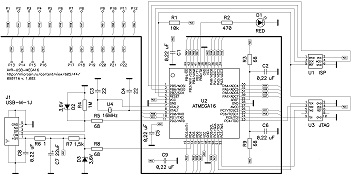
A detailed description of the board will not be here (who cares, see links). I can only say that the board already has all the necessary strapping for the microcontroller and USB - that is, you can plug the board into USB, it will be powered from it and the ATmega32 microcontroller will work. All you need to do is write a program for it (more on that later), and solder some construction to the board’s mock-up field (8x11 with 2.54 mm pitch). The board has 22 free I / O ports (mapped to two rows of holes), on which we can hang LEDs.
The possibility of flashing a microcontroller on the board using USB was also very important . Yes, no programmers are needed, only USB, since the ATmega32 already has a USB program loader (how to work with it, written on Habré, see links). For programming and debugging, you can also use the ISP and JTAG interfaces, but I didn’t need it, since so far I don’t have a programmer or an in-circuit debugger.
In my first experience on this topic, I decided to make a volume indicator in the system. On the board, I wanted to place several LEDs and write a program to control their power and visualize the sound on the computer.
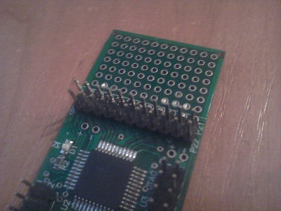
First of all, I didn’t want to solder everything on the purchased debug board, and using it as a “base” for separate “modules” designed for it would be separate small boards. That's exactly what I did. First of all, I soldered the lattice to the derived free ports of the microcontroller:
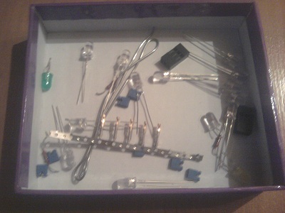
I also needed an additional cheap prototyping board (which it is not a pity to spoil with a soldering iron at my first soldering experiments), which I, along with all the necessary small things, bought on the radio market:
Further, it was not tricky - to solder the LEDs and resistors to them. The first time faced with the need to work with LEDs, I shoveled a lot of information to understand how it all works. I found all the necessary information on easyelectronics.ru , where it was described in detail “how and what”. Thank you so much.
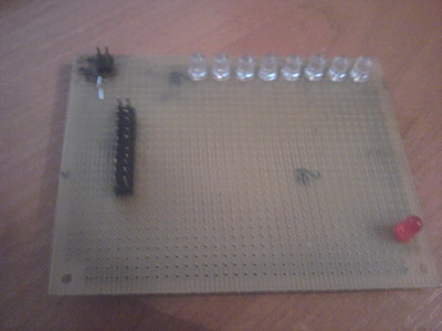
As a result, I got something like that (a connector and an uncomplicated circuit for connecting LEDs with a grid and a common minus) soldered onto the board:
Two boards with each other decided to connect using a loop from the old computer:
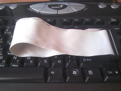
Thus, I have a modular system. I can quickly assemble new modules and use them with the same microcontroller simply by rearranging the cable.
It is worth noting that the board itself, unfortunately, and perhaps to the joy, does not have a built-in USB interface, so all communication between the computer and the board is done using the V-USB library developed by Objective Development Software, which is distributed under the GPL license.
The computer uses the libusb-win32 library for the Windows operating system (2000, 2003, XP) and libusb for the * nix family of operating systems (Mac OS, Linux, etc.).
Such an important part of the project as firmware ... I wanted to do it again, something simple but effective.
For some reason, I was very lucky at that time with searching for information and therefore everything was there on the above site, I found a great solution: firmware for MK, as well as a wrapper class written in C # (the most friendly programming language for Windows for me).
The firmware itself is written in such a way that its main task is to set the bit in a specific register, using data received via USB. The rest is handled by the desktop program.
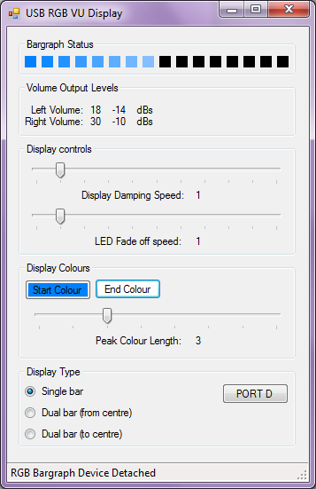
All you had to do next was to write a program that would send the necessary bits to the correct registers, using the aforementioned wrapper for C #. It should not be any work any more, all that is needed from the program is to get the current volume level in the system and change the necessary bit.
Having a little searching in the old folders, I found some unnecessary suitable workpiece, hidden for future needs earlier, written on the basis of AudioCoreApi (C #).
Well, it remains to arrange the necessary commands in the right events.
Since I connected the LEDs on the board to all the legs of the port A of the microcontroller, I accordingly need to “pull” the legs of the MK according to the LEDs. The state of each LED corresponds to the state of each bit in the PORTA byte (the byte that is responsible for the state of the microns on port A).
We find the main timer in the program and write the following code:
Here, depending on the volume level in the system, we use shift operations, set or reset a certain bit in hundler.PORTA, where hundler is the object to work with the device, and PORTA is an input / output port byte, implemented as follows:
The usb_control_msg () function is a function from the V-USB library.
Also, the important point is that before using port A, all its legs should be installed on the output, not on input (Speaking honestly, inadvertently skipping this moment in some articles, it knocked me up a bit when the LEDs were lit by a third power) in the following way:
Well, that's all! Thank you for reading up to this point. I hope the comments will not talk about the picture "how to draw an owl," everything seems to be clear and not very difficult as it seemed to me earlier. Also, I did not want to say this, but this is already half the way to the mood lamp :)
Ps I apologize for the poor quality photos and videos. Unfortunately, there was nothing at hand except a google phone.
What will be in the post?
In the post I will tell you about my experience in developing my first craft, which controls the LEDs on the board using a program on a computer, and more specifically some kind of volume indicator with a single visualization band. Here is the device:
')
Perhaps it will not be interesting for experienced radio amateurs, but there will probably be those who do not know where to start. This post I address primarily to people who first want to assemble any device to control it from a computer, without specific tools and necessary materials (such as solder paste, hair dryer) and without the need to draw and etch a printed circuit board. A design like the one described here can provide a person with a “quick start” so that he can understand what it is and also decide for himself whether he wants to do this business in the future.
Search for information
The search for information was supported by an article on Habré, Management of a homemade USB-HID LED, using the GUI shell on .NET . In this post, the author talks about buying a small debugging board AVR-USB-TINY45. I went through the author's links and found several ready-made debug boards there. AVR-USB-TINY45, which the author of the above post used, was not enough for my experiences, and AVR-USB162 was too cool for me (the LUFA library is complicated, and I couldn’t find any examples of host software), so my choice was on the board AVR-USB-MEGA16 with an ATmega32 microcontroller on board.
More about buying
The purchase of the AVR-USB-MEGA16 debug board together with the delivery and all the percentages for transferring funds via Webmoney (it turned out that it’s not so easy to replenish Yandex-Money in Kharkov) cost me ~ 26 USD. Delivery from Moscow to Kharkov was a bit tight (the parcel was stuck somewhere near Kharkov), but everything soon arrived. I would like to say a special thank you to microsin.ru - the board was securely packed and protected from impacts.
AVR-USB-MEGA16 debug card
A detailed description of the board will not be here (who cares, see links). I can only say that the board already has all the necessary strapping for the microcontroller and USB - that is, you can plug the board into USB, it will be powered from it and the ATmega32 microcontroller will work. All you need to do is write a program for it (more on that later), and solder some construction to the board’s mock-up field (8x11 with 2.54 mm pitch). The board has 22 free I / O ports (mapped to two rows of holes), on which we can hang LEDs.
The possibility of flashing a microcontroller on the board using USB was also very important . Yes, no programmers are needed, only USB, since the ATmega32 already has a USB program loader (how to work with it, written on Habré, see links). For programming and debugging, you can also use the ISP and JTAG interfaces, but I didn’t need it, since so far I don’t have a programmer or an in-circuit debugger.
Formulation of the problem
In my first experience on this topic, I decided to make a volume indicator in the system. On the board, I wanted to place several LEDs and write a program to control their power and visualize the sound on the computer.
Assembly
First of all, I didn’t want to solder everything on the purchased debug board, and using it as a “base” for separate “modules” designed for it would be separate small boards. That's exactly what I did. First of all, I soldered the lattice to the derived free ports of the microcontroller:
I also needed an additional cheap prototyping board (which it is not a pity to spoil with a soldering iron at my first soldering experiments), which I, along with all the necessary small things, bought on the radio market:
Further, it was not tricky - to solder the LEDs and resistors to them. The first time faced with the need to work with LEDs, I shoveled a lot of information to understand how it all works. I found all the necessary information on easyelectronics.ru , where it was described in detail “how and what”. Thank you so much.
As a result, I got something like that (a connector and an uncomplicated circuit for connecting LEDs with a grid and a common minus) soldered onto the board:
Two boards with each other decided to connect using a loop from the old computer:
Thus, I have a modular system. I can quickly assemble new modules and use them with the same microcontroller simply by rearranging the cable.
Software part
Communication
It is worth noting that the board itself, unfortunately, and perhaps to the joy, does not have a built-in USB interface, so all communication between the computer and the board is done using the V-USB library developed by Objective Development Software, which is distributed under the GPL license.
The computer uses the libusb-win32 library for the Windows operating system (2000, 2003, XP) and libusb for the * nix family of operating systems (Mac OS, Linux, etc.).
Firmware
Such an important part of the project as firmware ... I wanted to do it again, something simple but effective.
For some reason, I was very lucky at that time with searching for information and therefore everything was there on the above site, I found a great solution: firmware for MK, as well as a wrapper class written in C # (the most friendly programming language for Windows for me).
The firmware itself is written in such a way that its main task is to set the bit in a specific register, using data received via USB. The rest is handled by the desktop program.
Program
All you had to do next was to write a program that would send the necessary bits to the correct registers, using the aforementioned wrapper for C #. It should not be any work any more, all that is needed from the program is to get the current volume level in the system and change the necessary bit.
Having a little searching in the old folders, I found some unnecessary suitable workpiece, hidden for future needs earlier, written on the basis of AudioCoreApi (C #).
Well, it remains to arrange the necessary commands in the right events.
Since I connected the LEDs on the board to all the legs of the port A of the microcontroller, I accordingly need to “pull” the legs of the MK according to the LEDs. The state of each LED corresponds to the state of each bit in the PORTA byte (the byte that is responsible for the state of the microns on port A).
We find the main timer in the program and write the following code:
byte PortState = 0; for (int i = 1; i <= 8; ++i) { if (leftVolumeLevelPercent > 12 * i) { PortState <<= 1; PortState |= 0x01; } } hundler.PORTA = PortState; Here, depending on the volume level in the system, we use shift operations, set or reset a certain bit in hundler.PORTA, where hundler is the object to work with the device, and PORTA is an input / output port byte, implemented as follows:
public byte PORTA { set { usb_control_msg(handle, USB_TYPE_VENDOR | USB_RECIP_DEVICE | USB_ENDPOINT_OUT, RQ_IO_WRITE, value, aPORTA, null, 0, 5000); } get { usb_control_msg(handle, USB_TYPE_VENDOR | USB_RECIP_DEVICE | USB_ENDPOINT_IN, RQ_IO_READ, 0, aPORTA, buffer, 1, 5000); return buffer[0]; } } The usb_control_msg () function is a function from the V-USB library.
Also, the important point is that before using port A, all its legs should be installed on the output, not on input (Speaking honestly, inadvertently skipping this moment in some articles, it knocked me up a bit when the LEDs were lit by a third power) in the following way:
hundler.DDRA = 0xFF; // - 255, Well, that's all! Thank you for reading up to this point. I hope the comments will not talk about the picture "how to draw an owl," everything seems to be clear and not very difficult as it seemed to me earlier. Also, I did not want to say this, but this is already half the way to the mood lamp :)
Video
Links
- Manage a homemade USB-HID LED using a .NET GUI shell
- Description of AVR-USB-MEGA16 debug card
- Firmware and class wrapper in C #
- C # program from the post
Ps I apologize for the poor quality photos and videos. Unfortunately, there was nothing at hand except a google phone.
Source: https://habr.com/ru/post/125218/
All Articles