Router + GPRS modem = mini VoIP PBX or GSM gateway do it yourself
The other day there was a need to pick up telephony in a remote, small office.
A stable Internet channel, as in most remote regions, was not found in the campus, so the task was to create a budget PBX with a local GSM channel + VoIP connection with a central (corporate) PBX.
Solution Description
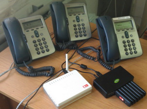
The system consists of:
1. Router - DLink DIR-320. Of course, it was possible to look at more productive ones (for example, ASUS RT-N16, 400 MHz versus 200 MHz), but the task is to collect a budget solution (4500r. Asus vs. 1500 Dlink).
2. GPRS modem - Huawei E1550, this choice is based on technical features, the reasons will be clear as you read the article.
3. USB Hub 7 ports - StLab, you can any other, most importantly - external power.
4. MicroSD Flash on 1GB - any (the volume can also be large).
Upcoming tasks:
1. We are flashing the router with “alternative” firmware.
2. Preparation of GPRS modem.
3. Mount the microSD card for the software installed on the router.
4. Install and configure the router IP-PBX Asterisk.
We are flashing the router with "alternative" firmware
This item is probably very “zamylen”, and so steadily I will cite a sequence of actions.
The firmware itself can be taken from here , its feature is the kernel version 2.6, because 2.4 does not support the processor timings, which is very necessary for both the asterisk and its chan_datacard module (with which we will use the GSM modem as a channel).
Due to the limitations of Flash of the selected router, Samba, FTP, SSH are excluded from the firmware, which can be easily installed later.
Firmware downloaded, it remains to flash. It is assumed that in the hands of the DIR-320 "out of the box."
At the root of the system disk on the PC (for convenience), create the “bin” directory, put the firmware into it and rename it to firmware.bin.
There (in the bin directory), create the flashing.bat script with the following contents:
@Echo Off
:BEGIN
ping -n 1 -w 1 192.168.0.1
If errorlevel 1 Goto BEGIN
If errorlevel 0 Goto FLASH
Goto END

:FLASH
Echo *** Start Flashing ****
tftp -i 192.168.0.1 put c:\bin\firmware.bin

:END
In the line "c: \ bin \ firmware.bin" we change the drive letter to our own.
Install the network card settings (to which the router is connected):
IP address - 192.168.0.2
Subnet Mask - 255.255.255.0
When the power of the router is off, press and hold the Reset button (the back panel of the router), turn on the power.
As soon as the LAN indicator on the router lights up, release the Reset button and run the flashing.bat script.
The firmware will take 1-2 minutes as soon as the status indicator lights up - reset the settings of the router, pressing the Reset button while holding the Reset button until the status indicator blinks.
Network card settings return to "receive automatically."
The IP address of the router is 192.168.1.1, the login from the WEB management interface is admin / admin.
')
Briefly required settings of the router:
1. Change Name - for convenience, you can change to root.
2. Change Password - change to your own.
3. Make sure telnet is enabled.
4. We try on the settings and restart the router.
GPRS modem preparation
In its “normal” state, the E1550 modem is seen by the OS as a composite USB device.
The router is hampered by the presence of a CDRom modem emulation with software, so we will disable it (emulation), and at the same time we will remove the binding to the operator's sim card.
1. We need a dc-unloker to enter commands and display the status of the device, you can download it here .
Swing, install.
2. Connect the GSM modem with a MicroSD card to the PC, wait for the installation of the drivers and the detection of the device.
3. Run dc-unloker and click "Search".
4. As soon as the device is found, we will see a brief description of it, listing IMEI, software version, and so on. Copy IMEI to clipboard.
5. Go to the OnLine page of the unlock code generator .
6. Insert IMEI and fill out the captcha. As a result, we get 2 Unlock and Flash codes (code for flashing the device). We need Unlock, copy to clipboard.
7. In dc-unloker you need to run 2 commands in the text window:
AT^U2DIAG=256 ( + Card Reader)
AT^CARDLOCK="<Unlock >"
The modem is untied from the SIM cards and does not emulate a CDRom.
We mount a microSD card for software installed on a router
1. Used software:
Putty
WinCP
2. We connect the modem to the router. Turn on the power of the router.
3. Using the Telnet protocol in Putty, we connect to the IP router 192.168.1.1, the login / password is admin / admin.
4. Using the fdisk utility to remove existing partitions from the card, the microSD will be visible as / dev / sda.
Execute commands:
fdisk /dev/sda
Command (m for help): p
If there are sections, we delete them sequentially:
Command (m for help): dIf there are no sections or deleted in the previous step:
Command (m for help): n
p
1
( Enter)
Command (m for help): w
5. The created section is formatted:
mke2fs -j /dev/discs/disca/part16. Mount the partition in the / opt directory
mount /dev/discs/disca/part1 /opt7. The following commands will later use ipkg to install packages from the repository:
mkdir -p /opt/tmp/ipkg
ipkg.sh update
ipkg.sh install ipkg-opt
ipkg update
8. Install the necessary (or simply convenient) software from the repository:
ipkg install mc ( )
ipkg install nano ( )
ipkg install opnenssh (SSH SFTP)
ipkg install asterisk16 (IP )
9. Configure automounting of microSD card and autorun of OpenSSH server and Asterisk:
in the / etc directory we create the fstab file, for example:
touch /etc/fstabopen (nano / etc / fstab) and write to it:
#!/bin/sh
/dev/discs/disca/part1 /opt ext3 rw,noatime 1 1
in the / tmp / local / directory create the .files file:
touch /tmp/local/.fileswrite to it:
/etc/fstabin the directory / tmp / local / create the directory sbin and in it the following files
mkdir /tmp/local/sbin
touch /tmp/local/sbin/pre-mount ( )
touch /tmp/local/sbin/post-mount ( )
touch /tmp/local/sbin/pre-shutdown ( /)
write to the pre-mount file:
#!/bin/sh
e2fsck -f -y -v /dev/discs/disca/part1 ( )
write to the post-mount file:
#!/bin/sh
/opt/etc/init.d/S40sshd ( OpenSSH )
/opt/sbin/asterisk ( astrisk)
write to the pre-shutdown file:
#!/bin/sh
/bin/umount /opt ( /opt)
assign execution rights to the scripts:
cd /tmp/local/sbin
chmod +x /usr/local/sbin/*
save all changes in non-volatile memory:
flashfs save
flashfs commit
flashfs enable
reboot the router:
rebootAfter downloading, if everything was done correctly, you can connect to the router via SSH and SFTP.
Installation and configuration on the router IP-PBX Asterisk
We performed the Asterisk installation in the previous step, it remains to configure it.
To start, download the archive with the chan_datacard module from here (you can compile it yourself, but I don’t want to describe the whole build process, so I’m posting it).
The file chan_datacard.so is copied to the / opt / lib / asterisk / modules / directory
Copy the datacard.conf file to the / opt / etc / astrisk / directory
In the /opt/etc/astrisk/modules.conf config we write (it is advisable to save the original to another place):
[modules]
autoload=no
load => format_pcm.so
load => codec_ulaw.so
load => codec_alaw.so
load => app_dial.so
load => app_macro.so
load => app_playback.so
load => app_setcallerid.so
load => app_disa.so
load => app_transfer.so
load => func_timeout.so
load => func_callerid.so
load => func_logic.so
load => func_strings.so
load => pbx_config.so
load => pbx_spool.so
load => chan_sip.so
load => res_musiconhold.so
load => func_shell.so
load => func_channel.so
load => chan_datacard.so
load => chan_oss.so
In the config /opt/etc/asterisk/datacard.conf we write (note, in this config 2 modems are connected):
[datacard0]
context=datacard-incoming ; context for incoming calls
audio=/dev/ttyUSB1 ; tty port for audio connection
data=/dev/ttyUSB2 ; tty port for AT commands
resetdatacard=yes ; reset datacard during initialization
disablesms=yes
rxgain=3 ; increase the incoming volume
txgain=3 ; increase the outgoint volume
group=1 ; calling group

[datacard1]
context=datacard-incoming ; context for incoming calls
audio=/dev/ttyUSB4 ; tty port for audio connection
data=/dev/ttyUSB5 ; tty port for AT commands
resetdatacard=yes ; reset datacard during initialization
disablesms=yes
rxgain=3 ; increase the incoming volume
txgain=3 ; increase the outgoint volume
group=1 ; calling group
In the config /opt/etc/asterisk/sip.conf, we write (it is advisable to save the original to another place):
[general]
context=from-pstn-unauth
allowoverlap=yes
allowguest=yes
alwaysauthreject=yes
bindport=5060
bindaddr=0.0.0.0
srvlookup=no
nat=yes
canreinvite=no
insecure=invite
tos_sip=cs3
tos_audio=ef
tos_video=af41
disallow=all
allow=ulaw
allow=alaw

[101]
type=friend
defaultuser=101
secret=test
host=dynamic
context=test
disallow=all
allow=alaw
allow=ulaw
In the config /opt/etc/asterisk/extensions.conf, we write (it is advisable to save the original to another place):
[general]
static=yes
writeprotect=no
autofallthrough=no
clearglobalvars=no
priorityjumping=yes

[globals]

[test]
exten => _8XX.,1,Dial(Datacard/g1/${EXTEN})
exten => _8XX.,n,Hangup()

[datacard-incoming]
exten => _.,1,Dial(SIP/101)
exten => _.,n,Hangup()
Make sure that the sim cards used in the modem do not require a PIN (otherwise disable).
We reload the router.
We connect the SIP client to the server with account 101@192.168.1.1 and the password test.
Incoming calls will go to this extension.
Outgoing calls will be sent via GSM modems.
PS: the asterisk settings are provided solely for educational purposes, to build a demonstration stand, for use in combat mode, I recommend to study the Asterisk documentation.
Source: https://habr.com/ru/post/125186/
All Articles