Telepresence Trolley from the materials at hand
 Good afternoon, dear users.
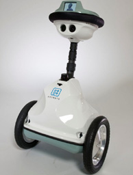
It all started with the fact that once in the news I saw a telepresence robot from AnyBot (on the left in the picture). It was already their second robot, the cost of which they managed to reduce by as much as twice, from 30 to 15 kilo dollars. This sum seemed to me a bit too big for a “webcam on wheels”. Although I’m a little clever here, this bot has a very good main camera with high resolution and optical zoom, plus an additional “navigation camera”, omnidirectional and narrowly focused microphones and other amenities of professional devices. But, nevertheless, for the same money you can buy a brand new car. Therefore, out of a purely sporting interest, it was decided to make the simplest telepresence device out of improvised means and at minimal cost. "Under the arms" were Daddy's Toshiba Satellite laptop with a dead battery and a live LPT port, a gearmotor of a power window of its own Niva and another different small things.
What came out of this can be found under the cut.
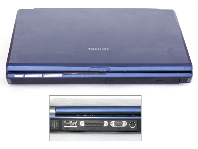
A laptop:
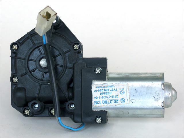
Gear Motor:
')
Mechanical part
First you need to solve the problem of power laptop. To do this, you have to take on board a UPS with an extra battery to last longer. At the same time, in addition to 220V for a laptop, we divert 12 volts to power the engines. Thus, the dimensions of the trolley are determined by the size of Toshiba and Ippon.

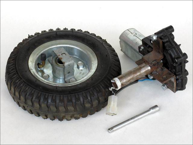
We select the simplest wheel layout: two main wheels with separate drive, plus a pair of freely rotating furniture wheels. To do this, you need to purchase a second geared motor from the opposite door. I didn’t experiment with driving wheels, I bought a “classic” of Russian robotics - Chinese PR-1400. They are quite comfortable and already come with bearings.

The ways of connecting the engine with the wheel each invents its own, but the idea can be used and ready, for example, "Techno-Vision" . You can also buy this assembly in the same place. But this option does not suit me, since one node costs more than the entire budget of the trolley. So do it yourself. The main part of the unit is easily cooked from scraps of the building corner and 1/2 inch water pipe, modified with a file to the desired diameter. Of course, it is better to use a lathe or find a more suitable pipe, but I haven’t found either one or the other. As the drive shaft it is very convenient to use the socket wrench head extender. The leash on the wheels is bent from a suitable metal plate. In my case, it turned out to be a flattened corner for attaching shelves. Unfortunately, the metal of the leash turned out to be soft, and because of it there was quickly a backlash, while the head extender was sitting on the engine shaft, as if it was poured.
The cart itself is assembled from an aluminum corner and a 25mm square and a piece of galvanized to the bottom. We fasten the wheel assemblies to the bottom frame, where they are very compactly placed.
Trolley assembly:
Mounted wheel unit:
That's all the basic mechanics ready, now proceed to the head. You can, of course, limit your webcam, especially if you find a camera with tilt control like a Logitech Quickcam Orbit AF Web camera, or use a security camera with a video capture module. But I did not dare to spend money on anything else, since I already had a certain unnamed camera, so we’ll use it. One of the drawbacks of conventional webcams from the point of view of navigation is that the viewing angle is too small, which can be extended with special attachments that are sold in online stores. I did it easier - I cut the door peephole, pulled out a diffusing lens from it and glued it to the camera lens. Also for navigation, it is desirable to be able to lower the camera and look "under the feet." So, collect the head from the remnants of the corner and zinc on the hinge of a bolt. Attach the camera and laser pointer as your index finger. To drive the tilt of the head, you can use a servo for radio models or any engine with a gearbox. In the same garage, I found a broken mirror with electronically controlled tilt from "our" Chevy Niva (by the way, it turns out that the mirror drive module was made in the USA, and the engine itself in China, that's almost a world tour, he made before he got to our cart ). The speed of the output shaft of the gearbox of this engine is very low, about 1 turn in 4 seconds, which is very convenient. We connect the shaft pivotally with the base of the "neck" and the drive tilt is ready. Although to limit its movement it is worthwhile to add limit switches with parallel diodes, which I did. Thus, when the voltage is applied, the motor lowers the “head”, reaches the limit switch, and stops. To raise the head - you need to change the polarity. We make papier-mâché head covers, although anyone who is friends with fiberglass or other materials can use them.
The idea to putty the resulting lid with an acrylic putty left over from the repair was not very successful, which was amply demonstrated in the photo. But for the experiment is not critical. It remains to put the received head on the folding handle from the Chinese mop and to fasten it to the trolley (I provided all disconnectable connections with wing nuts so that the high construction could be disassembled during transportation).

At this “iron” works are finished, although I still inserted pieces of plastic panels between the upper and lower tiers to hide the insides.
Electronic part
Now you need to connect the computer with the engine and a laser pointer. Having an LPT port makes it a lot easier because you can do without an external controller. Of course, on modern LPT netbooks you can’t find a port in the afternoon with fire, but on nettops and thin clients on nano or mini ITX they usually exist. So, we need a driver to control the motors using a small current and voltage port with the possibility of reverse. Since I am an absolute noob in radio electronics, I chose the simplest driver circuit for switching relays for reverse and a field N-channel transistor for speed control.
The speed will be adjusted by pulse-width modulation (PWM ohm), that is, quickly turn on / off the power and, depending on the ratio of the on and off state, the speed will also change. The main engines we consume no more than 10 amps. Based on this, we select the components. It is advisable to find the relay with two groups of switches and it should be designed for our current, or you can take a pair of 5-contact car relays. I used the field transistor without an additional driver. It is simpler in terms of circuit design, but imposes some limitations. Firstly, a low-voltage opening transistor is needed, for example, an IRL series, secondly, a small LPT port current cannot recharge the gate quickly (more precisely, the parasitic capacitance between the gate and the transistor channel), which means the PWM frequency cannot be large. This is not critical, but the engine will make more noise than when using ultrasonic frequencies. The TO-220AB transistor in the case without a radiator dissipates about 1 watt. Accordingly, the channel resistance in the open state should be less than 0.01 ohm. This is the second important characteristic of the transistor. The diodes on the circuit are needed so that the reactive current of the inductive load can go even when the transistor is closed and does not lead to its breakdown. And the engine in this case will rotate without braking when the power is off, which is important for PWM. Diodes must also hold a current of 10 amps. I did not find such and turned on two 6 amps in parallel. Thus, we get two bits of control of each engine: one - turns on the power, the second - reverse.
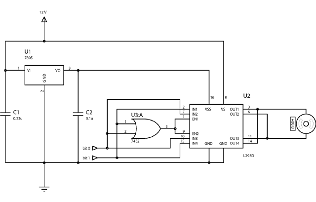
The head tilt motor in us consumes an order of magnitude less current, so you can use the finished chip driver L293D. This is a four-channel motor driver with built-in inductive load protection diodes and the ability to supply up to 0.6 amps per channel. Such a microcircuit can be controlled by four collector motors without reverse, two collector motors with reverse and one four-pole stepper motor. Since we have only one motor in our head, I combined the channel pairs, thereby increasing the possible load current to 1.2 amperes. Now let's deal with the management. In fact, we get three control bits: one turns on the microcircuit (enable), the second supplies voltage to one channel of the engine, and the third to the second channel. For PWM, the documentation recommends turning the entire microcircuit on and off (more precisely, half if not soldering them as I did) instead of one of the channels, since in this case the engine will not actively slow down. But the three bits of control seem to me unnecessary, so we reduce them to two, since we have only four combinations. To do this, we add another chip - a logical "OR", feed the state of the channels to the input, connect the output to the enable input (enable) of the driver. Thus, we cover all possible engine states with two bits: 00 - free rotation (for PWM-a), 01 - rotation in one direction, 10 - rotation in the opposite direction, 11 - braking.
Since we have logic chips on the board, we need 5 volts for their power supply. The easiest way to make 5 volts out of 12 is to use a linear stabilizer (LM) 7805 (or the domestic equivalent - KR142EN5). It is not particularly suitable for large consumption, but for two microcircuits of standard logic it is more than enough.
It remains to connect a laser pointer. My pointer was powered by 4.5 volts and a couple of tens of milliamperes. That is, it can be connected directly to the output of the LPT port. But it turned out that the logical unit of my laptop on the LPT port is far from reaching 5 volts and the pointer almost does not shine. So I had to use the “OR” chip once again as an amplifier.
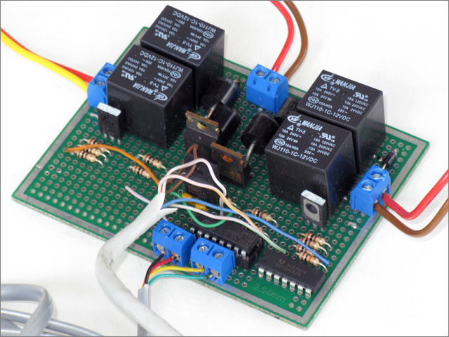
Well, with the scheme and components sorted out, now it remains to solder and dissolve everything. I did not find the laser iron at home, so I used a breadboard model, which turned out to be quite convenient. On the side of the board, he left space for Arduino Nano so that it could be easily migrated to the platform without an LPT port.
So, all the iron is collected, it remains to set it in motion.
Software part
From a programmatic point of view, there are several implementation options. You can write a separate client server, web service or not reinvent the wheel and use Skype. He has already implemented two-way audio-video streaming, chat and an additional channel that can be used for control. What we choose.
Server
Server tasks: receive calls from Skype, receive management commands and move the cart.
First, teach him to manage our bot. I have Windows on my laptop, so we’ll write for it. Unfortunately, Windows XP does not allow working with ports directly, but the Internet inpout32.dll was found on the Internet, which allows you to bypass this limitation. Now we have the ability to control every bit of the port directly. To count the time intervals, I used a multimedia timer (function timeSetEvent), which allows you to set intervals of 1 ms. In the handler for each engine, we count the number of ticks on and off and switch the output bit of the engine on depending on the current speed. Thus, it turns out that the field effect transistor is in each state for at least 1 ms, which is more than enough to recharge the parasitic capacitance. True, the PWM is not quite normal; not only is the pulse duty cycle changed, but also the frequency, which is audible when the engines run. We also limit acceleration by software so that the cart is not too jerky. We make a software interface for controlling the cart as a separate object and you can go to Skype.
Skype provides a fairly simple interface to interact with external applications. Each operating system has its own, but it is based on a common asynchronous text protocol. The server part of us will act as follows: answer an incoming call, turn on the video, accept commands from the caller. To send commands, you can use Skype chat, as done in the project Sparky , but cluttering up the chat is not very good. Moreover, Skype provides the ability to directly communicate between applications using application to application commands (AP2AP). There are two data transfer options: the first one resembles normal TCP sockets with connection establishment and acknowledgment of receipt, the second - UDP datagram, that is, just sending a message without setting up a connection and confirming. Just in case, on the server side, I implemented receiving commands through all three protocols: chat, sockets, and datagrams. Thus, it is possible to control a bot without a client plug-in, via chat. As a passive protection against delays and a communication break, I forced the bot to stop after 300 ms after receiving the last command. During this time, he will travel no more than 20cm at maximum speed.
Customer
The client is quite passive. Once launched, it can be minimized. What it does: it connects to Skype, waits for the initiation of the call, after the call it tries to establish a connection with the user who calls AP2AP, if it succeeds, starts tracking the keyboard and mouse and sending commands over the established connection. Management is captured in any window by pressing Ctrl + Alt. Thus, you can control the bot directly from the video chat window.
The source code of both programs can be found here .
results
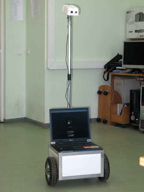
Full-length bot:
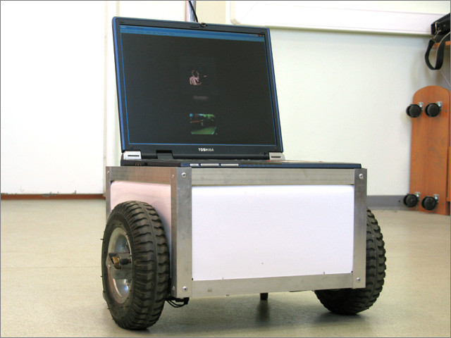
Trolley close-up:
On the video you can see how she rides:
All features in one list:
- management via Skype (the client is only for Windows, but through the chat you can manage it from the phone);
- connection to the network via WiFi;
- 2 degrees of freedom of the trolley (moving back and forth, turning, including on the spot);
- tilting head;
- viewing angle ~ 80 degrees horizontally;
- laser pointer, combined with the center of the image on the camera;
- variable head height;
- low center of gravity (accidentally knocking over the cart is quite difficult);
Expenses
Costs are difficult to determine completely, since most of the components were found in the “bins of the motherland”. But you can roughly estimate:
- main wheels (PR-1400): 2 * 465 = 930r;
- engines from power windows (in fact, I bought only one): 2 * 550 = 1.100r;
- structural elements (profile, extensions heads, furniture wheels, bolts, nuts, washers, rivets): ~ 500r;
- electronic components (breadboard, relays, transistors, diodes, microcircuits, connectors, ...): ~ 500r.
Total: ~ 3.000r.
To this still need to add:
- computer (tablet computer, netbook, nettop, thin client, or self-made from Nano, Mini-ITX ...): 5.000 ~ 25.000r;
- camera, if not satisfied or there is no built-in (webcam, analog surveillance camera + video capture card, IP camera): 200 ~ 30.000r;
- batteries and charger (UPS or separately, lead or lithium): 1.000 ~ 10.000r;
- controller (if there is no LPT port, or it is not enough): ~ 1000r;
- engine for tilting the head: 200 ~ 500r.
Thus, you can meet in 10.000r, using the cheapest components, and in $ 2.500, using some of the most expensive.
Todo
It is clear that this is the most basic implementation of the telepresence robot, so I never called it in the course of the article. What does he lack for full-fledged work? Let's try to list:
- more reliable engines (window gear motor not designed for long work);
- ultrasonic motor driver;
- speed control encoders (engines work a little differently, and the trolley does not keep a straight line);
- external controller for engines;
- ultrasonic, infrared or laser collision avoidance sensors;
- better microphone (two are better - everything is directional and narrowly targeted);
- a better camera (two are better - a fisheye for navigation and a regular one with an optical zoom);
- charging base;
- some degree of autonomy to simplify management (bypassing obstacles, following the target, returning to the base);
- decent housing;
That is, it is easier to remake everything from scratch.
Of course, if all this is implemented, the cost will increase again in 1.5-2 in relation to the highest estimate from the previous section and will reach $ 3,500 ~ $ 5,000. Plus work, taxes, room rental, software development. So, piece-making of high-quality telepresence robots is not such a cheap pleasure, as it seemed in the beginning, but for your own needs you can make very little.
useful links
- Skype public API .
- Discussion of drivers of collector engines .
- Handmade: Sparky ; A Self-Docking Telepresence Robot ; iRobot + Netbook .
- Commercial examples: Anybots ; Jazz ; VGo ; Giraff ; RBot ; SuperDroid RP2W .
- Texai (the same Sheldon) .
Source: https://habr.com/ru/post/124700/
All Articles