As I wrote to the skad
Introduction
This story began about a year ago. I myself am a specialty machine gunner, engaged in the development and implementation of automatic process control systems (APCS). The main job is to develop application software in specialized software, the so-called SCADA package. For those who are not familiar with the concept of SCADA and what it is eaten with - you can read in detail here . He worked for a company of a domestic developer of such a system for a long time, starting with a tester, went through technical support, grew to the level of the head of the system integration department, and developed turnkey automation projects based on software developed by the company. In the process of developing projects, finding himself in the shoes of an end user with a product, often had to modify the toolkit for specific tasks with a file, because the functionality was either buggy or did not reach the proper level. And all the debate on the development and marketing of product development either rested on the reluctance to do anything on the development side, or everything was attributed to the fact that my hands are crooked and I do not understand anything in sausage cuts. It could not go on like this for a long time, and at one fine moment our paths diverged with this company, I went to one of my large customers to continue to do what he did to order, but on the staff of this customer.
In my free time, I helped people and acquaintances from this area through their projects as an elective. Thanks to many years of work in this area, I have a lot of good contacts, and my reputation as an engineer has grown strong. Sometimes I was even officially bought from a company for specific projects as a development consultant. My projects and experience in the field of automated process control systems can be found here .
Initially he was engaged in automation systems for dispatching engineering systems of buildings in Moscow. Then, with the development of Internet technologies, the opportunity to develop projects for remote sites in other cities. The customer connected a dedicated secure channel of communication with the object via the Internet, which made it possible to directly connect to the object and adjust and fine-tune the project right from home. He continued to work on the same software as before, because the most appropriate alternatives have not yet been observed, and there were already very good practices and experience of previous developments, which I did not want to just leave when switching to new systems.
In the process of working on projects, the SCAD itself was working on its own patches, which allowed replacing the regular functionality of the package due to its poor performance or inability to implement certain requirements. During this revision, the system began to resemble a certain core, which was hung with external utilities and services like a Christmas tree toys. And so, looking at the result of such mockery of the package, a seditious thought began to creep in: why, in fact, do we need a blacksmith? In addition, a strong incentive was the fact that the developer of the SCADY continues its way of accumulating bugs and glitches, releasing all new releases, without being engaged in normal testing and elaboration of the product architecture. And since I was engaged in some development in my spare time, I felt very sorry for killing my free time for disassembling the bugs of someone else’s system, which often lasted half a night and so on for several nights in a row. Yes, and customers began to be outraged: for what kind of money was paid, then a lot of mistakes come up during commissioning on the basic functionality, then this very functionality really does not reach the declared and need something to connect or develop, although marketing tunes are corrupt managers about the mega-power of the package for the customer were naps about the exact opposite. As a result, overflowing emotions over the edge sat me behind the wheel of a vacuum cleaner (read the PC), and I decided to write my own SCAD.
Since this is primarily a tool for myself, I decided to do it not as required by advertising slogans, but since I see this tool as a project developer for an automated process control system. The architecture of the system that was already known to me for the long years of work of the Scada package was chosen as the main system architecture. I decided not to engage in the invention of a bicycle, but to pay attention to its functionality.
Everything would be great if it were not for one BUT - initially I’m not a programmer, but a machine gunner. What I wrote my own utilities for the package was something like a third-party hobby, a hobby, so to speak, for which I began studying the .Net technology and the C # programming language. Before that, I didn’t do anything serious and many of my knowledge in the field of programming and some technologies were at the level ñ I heard somewhere, or I’ve already seen how it works for someone. However - the eyes are afraid, and the hands do.
Many of my friends and colleagues, having learned about my idea, reacted to this as one — by rotating the index finger at the temple. Of course, all brands in this area have been made by development teams for years, and for years they lick themselves to get at least a little closer to perfection. But, in spite of such a reaction, I nevertheless began to carry out my plans. And here also the phrase of Genghis Khan, heard somewhere, became simply my motto: “If you are afraid, do not do it, and if you do, do not be afraid!” Taking the keyboard in my hands, I sat down to design my first serious system. Looking around the resulting scope of work, he began to be surrounded by books on programming in C #, as well as links to thematic forums, where he scooped all the necessary information on the principles of implementing certain functions in the package. But more about that below and in order.
Architecture
Before starting work, I compiled a certain functional map of the package for myself, what basic elements it consists of and what knowledge (what technologies) are needed to create these elements.
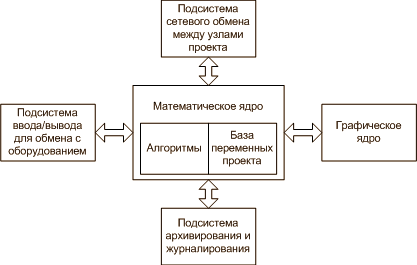
In general, the system loomed as follows:
')
In the center is the mathematical core, which performs the recalculation of the project structure consisting of a certain database of variables that are interconnected by logical connections. In addition to the base, there are algorithms in the project with which the project variables are also associated. These algorithms are created by the project developer, they perform the functions of controlling and monitoring the technological object through a database of variables that are associated with the control object itself (sensors and actuators) through the I / O subsystem through hardware (controllers, I / O boards, distributed data acquisition devices and management). In order for the operator (if any in the system is meant) to demonstrate all this colorfully and intuitively clearly, and also to provide him with the ability to control the technological process, a graphic input / output subsystem is provided, which displays the previously developed screens of the system elements in the form of mnemonic circuits , images, indicators, trends, sets of graphical objects consisting of standard primitives and various kinds of controls (buttons, sliders, minute response to a mouse click, etc.). Since the system implies a function of maintaining history in the course of the technological process, the parameters of the database of variables must be able to be saved to some archives so that they can then be raised to trends or reports in order to analyze the situation by technologists and operational personnel. Also, the same archives should store logs on events in the system - these are certain text messages with certain categories (message, warning, accident, error, operator action), time stamps of occurrence, acknowledgment by operating personnel and text describing the essence of the event. All this should be done by the subsystem of data archiving and event logging. Since the project of an automated process control system is often a multi-node system consisting of several operator sites, server nodes, controller nodes at the lower level, gateway machines, all of this is connected by an Ethernet network and requires prompt interaction in a quasi-real mode. This interaction should be carried out by the network exchange subsystem. Here is a brief summary of the overall architecture of the complex. We now turn specifically to the technologies that will be required to implement these subsystems:
Mathematical core - here the main emphasis should be placed on the development of an object-oriented model of the internal structure of the project itself, consisting of certain components (project variables), which are descendants of the base class with a specific set of properties, interfaces and methods that implement data processing algorithms variable in quasi-real-time mode (signal filtering, scaling, arbitrary user processing algorithm based on the developed program, or is it a fixed function depending on the type of the variable). The processing of this base by the kernel calculator during project execution at the node of the operator's automated workplace (the automated workplace of the operator) or the controller is performed cyclically with a certain recalculation cycle, which allows organizing continuous execution of logic in the executive module.
Algorithms are a separate topic for discussion. Historically, an automaton was not originally a programmer and knowledge of high-level languages was not a mandatory requirement for him. In addition, the requirements for support and readability of algorithms by other developers have resulted in the emergence of an international standard (IEC61131.3) in this area for 5 programming languages - three of them are visual, two are textual. In addition to the standard, many manufacturers of SCADA systems also support scripts - programming in high-level languages (for example VB), or the like (for example, Ci-code, something like C). My system was not an exception in this sense either, but I will tell about it in a separate article, which I plan to devote to my algorithm editor. The technologies that were drawn in this direction did not please me at all, because for the implementation of such a task it is necessary: write your own editor (especially interesting was the task of creating an editor for a visual programming language), a compiler, and also a calculator for executive modules that would execute and calculate algorithms in the project when the project is launched in continuous execution mode on the object. The perspective was drawn by her, even began to stock up with tons of literature on this subject and prepare to study the principles of building compilers in order to master this work. But about the details later.
Graphic core - this subsystem implied one fairly large section of work: develop a vector editor for drawing mimics. Moreover, the subsystem should be able to work both with a static image and with the dynamics of individual graphic elements, for example: dynamically changing fill colors for a graphic primitive in execution mode depending on the value of a project parameter (indicators), displaying the values of variables on the screen to operating personnel in the form of textual and graphic forms. In this case, everything should be:
- Beautiful (very often the end customer bites the beautiful interface, many ryushechek and animachek are mistaken by him as a direct proof of the coolness of the system, and for the authorities, in general, the first sign of evaluation of the system to make a decision about its purchase).
- Functional
- Convenient to develop
At first, I thought to solve this issue by licensing already ready libraries of graphic engines. I learned for myself a new word in this area: Canvas. However, examining the issue and comparing the cost and labor costs for licensing third-party tools came to the conclusion that I wanted it or not, but I would have to write my own vector graphics engine from scratch. At the same time, this prospect pleased me very much by the fact that, until that time, I had some idea how to draw a line on the screen with regular functions of the language and paint it in the desired color. Yes, I had to sweat a little, reading the thematic forums of programmers, where, as it turned out, the issue of implementing a vector editor constantly popped up among the people, and there were many developments and solutions, among which it was necessary to choose the most convenient for their direction. Well, along the way, a decent amount of computer graphics literature for programmers was also studied, now I even know what GDI + is and what it is eaten with. I also plan to devote a separate article to the implementation details of the graphic editor, in which we will try to consider in detail what has been done and what has come out of it.
Archiving and logging subsystem - this section was a serious stumbling block in the SCADA-system in which I had previously worked. There, the developer took the path of the invention of the bicycle and the closeness of the archives for external funds, which automatically made the system indigestible in many projects, since it was necessary to have access to the archived data also for third-party tools. And the bugs in the implementation made it simply non-functional with serious use in large projects. By the way, all this led many users to completely abandon the standard archiving system. The main requirements for this subsystem were primarily: its openness and convenient access to information for analysis and generation of reporting forms by the operational personnel of the technological object management system. The most convenient solution to this issue is the use of a relational DBMS. Many brands, by the way, also follow this very path; they store historical data and journals in relational DBMS. This is probably the only version of the subsystem with which I have already indirectly worked to some extent, because before that I had done one of the patches for SCADA exactly the subsystem for collecting and archiving data and event logs from SCAD to external relational DBMS. Following my current solutions, I chose MySQL as the basis for the DBMS and, as a communications provider, the modern ADO.Net technology.
I / O subsystem for exchange with equipment - in this subsystem the main issue is to support fairly common open international standards from manufacturers of hardware for automation (an example is the ModBus protocol in all its implementations), as well as software interfaces for exchanging with external software (here the primary role is played by the OCR interface - OLE for Process Contol). I also cover a separate article on this topic, where I will describe my vision of the implementation of hardware support in my software package, the specifics of implementation, and what came of it.
The network exchange subsystem between project nodes — due to the fact that not all automation projects are limited to a single operator workstation, and consist of multiple nodes, a data exchange mechanism is required between them. Moreover, both real-time data (operational) and archival data (data vectors with time stamps, samples, arrays). This section of the system is still under development, so I will prepare and publish more detailed information a little later, as soon as the main development work is completed.
What is the result of all this?
I started my work in this project from scratch in the literal and figurative sense somewhere in April of 2010. He worked in his free time mainly in the evenings. The start-up garage has practically turned out, because for work I occupied a kitchen in a one-room apartment, where I sometimes stayed up until morning, stuffing the code and studying the literature. The whole development of the main components took a little less than a year: in the fall, I made the kernel, the visual editor of the algorithms, the editor of the project structure, developed the project model and the project file storage structure (all based on the XML format). At the same time I registered the archiving subsystem, its main engine in the runtime kernel of the executive system. On New Year, I started a graphic editor. Praise the New Year holidays, there was a time to thoroughly study this issue and choose the right path. By the beginning of spring, I had almost finished the graphics and in the spring I modified the mathematical engine with support for algorithms on pure C #. At the beginning of summer, I modified a little I / O subsystem in terms of support for the OPC interface. And now I am engaged in the network exchange subsystem.
Here are some functional statistics on the project:
- There is an instrumental system and two runtimes (execution modules, under which the initial automation project is launched at the facility): one for MS Windows (for AWPs), the other for WinCE (for controllers).
- Runtime under Windows supports both graphics and mathematics. Under WinCE - only math, because while in the controller while the schedule is not particularly required.
- The system itself supports two programming languages: FBD and pure C #
- In the system itself, at the kernel level, I developed my own model of working with data - the system does not work with data types, but with the concept of “object”. This has resulted in a lot of interesting things in the field of type casting at the system functional level: for example, a single arithmetic FBD block of addition, thanks to this technology, can add not only numbers, but also strings, or different types of data among themselves
- Implemented the ability to work and processing in the system of dynamic arrays, and with the help of its data processing model, they can be of mixed type and different functional: hello local archives and buffers for PAZ and PAC systems! The possibility of algorithmic processing of dynamic arrays of any data type. This in many SCADA packages is simply impossible in principle.
- All archiving and event logs are completely in relational DBMS - while MySQL.
- A system state save file is maintained between runtime restarts (dump). The dump format is XML.
- Due to the fact that the project itself is stored in an open XML format, the system allows group development of the project using standard repositories.
- All import-export (screens, programs, the project itself), even graphic libraries built on the XML format, is completely open and can be used by the developer at his own discretion to work with him using his own or third-party tools.
- According to the schedule I tried to get as close as possible to the quality of modern systems, but at the same time do not focus on very sophisticated graphics acceleration technologies, which for the most part often do not accelerate it, but only make it heavier and inhibit it in practice, but this did not prevent it from being beautiful. For example, a few examples of graphic screens:
Screenshot 1
Screenshot 2
Screenshot 3
Screenshot 4
Screenshot 5
Screenshot 6
Screenshot 7
Screenshot 8
And here are examples of comparing screens for identical projects in my system (left) and one of the brands (right):
Screenshot 1
Screenshot 2
Very great emphasis is placed in the toolkit on debugging functions for the project, therefore the toolkit supports:
- Online editing of algorithms right in the course of project execution in the debugger.
- Online editing of graphic screens is also directly in the process of executing a project in the debugger.
- Online editing of the project structure is also in the process of its implementation in the debugger (in general, Scada itself turned out as a single medium for online development).
- Built-in project corrector - can track logical errors that the developer could allow and point to them with auto-positioning on the project component where this error was found.
- Built-in automatic tester of the project - allows you to create scenarios for auto-driving of the project, up to the proclamation of the graphics screens, in order to verify its correctness.
- The built-in mechanism for developing mathematical models based on standard algorithms on FBD or C #, which are connected to hardware descriptors and the project can be transferred to debugging on models instead of real hardware and back almost in one click.
- The built-in debugger in the developer's environment allows you to debug projects with a distributed architecture as a whole within a single PC, with imitation of inter-nodal connections and the ability to access, track and change hands of any system parameter in the debugging process.
Currently, the following interfaces are supported for exchanging with external devices and devices:
- ModBus TCP (supported by RTU, but not yet enabled)
- OCR DA
- ICP-CON protocol support: I-7000 Series PCO
You can enumerate a lot and for a long time, so here I brought the most basic and large "chips" of the system ... You can get acquainted with the rest in the process of interaction with me.
There is also an opportunity to watch demos, demonstrating the principles of the system.
Online editing of algorithms on FBD in the process of debugging a project:
Online graphics editing during project debugging:
Demonstration of the capabilities of the engine for processing types in real time (FBD programs):
An example of a project with an algorithm in C # demonstrates the formation of a report in HTML format:
An example of the work of the automatic project corrector:
An example of developing a simple project. The plot is as follows: a simplest project is being developed, in which the controller is connected to the IO I7017 module from ICP-DAS, the first input of the module is connected to the sensor.
The value of this sensor from the controller rises to the AWP operator. The debugging of the project is demonstrated:
- First, in the debugger, the operation of the project is simply manually checked, the value of the sensor input is set manually, then through the DCO panel of the debugger
- Then, within the project, a mathematical model of the simulator on the FBD is created by standard means and connected to the ODR
- The work of the project with this simulator in the debugger is checked. Real-time simulator can be disconnected or connected with one mouse click
- Without stopping the debugging process, the mathematical model of the simulator that we connected to the ODR is being edited.
- Without stopping the process of debugging the project, edit the project parameters - primary signal processing in the form of a multiplier in the channel
Well, and so on, right down to the graphics ... The entire project, of any distributed architecture, even without the presence of hardware, simply creating models of simulators directly in the project and linking them to the ODR, creating, editing and debugging the entire project on one PC.
Fast duplication of developments in graphics with convenient re-binding of dynamized properties in the copied group of graphic elements. That is, the developer does not need to manually sort through all the properties in the new copied group in order to bind it to the new arguments to dynamize the new instance — the system automatically scans the group itself and makes a list of bindings, where the developer quickly reassignes the bindings with the DnD operation.
Download link
When working with graphics, the system provides the developer with a convenient mechanism for grouping and accessing screen components without compromising the integrity of the groups.
Drag-n-Drop functions when moving graphic elements between groups, moving blanks to the library. Import-export libraries to external files in an open XML format for sharing with other developers or saving work for future use.
Selecting elements through the screen with auto-positioning in the list of screen elements, or through the list itself allows you to access individual properties of any graphics component without breaking the overall hierarchy.
An example of symbiosis of two languages within a single program algorithm: FBD + C # code.
Particular attention should be paid to the fact that the C # code can also be modified without stopping the computation of the program as well as the FBD in real time. Very handy for debugging logic.
Vector animation in graphics: moving through the nodal points. Numeric parameter
String parameter
Developing your own visual devices for graphics: a pointer device.
Block histograms
An example of the use of library graphics resources for the rapid development of graphics.
The peculiarity of the editor is that he “remembers” which properties of graphic primitives were dynamized during the development of this element before being placed in the graphic library. When the developer inserts it into the screen from the library, the system scans the item and makes a single list of these dynamizations. On this list, any dynamization can be tied with a drag-n-drop or to an already existing screen argument, or also a drag-n-dropping dynamization, simply create a new argument and the system will tie it across all object dynamizations with an automatic machine, where he participated. In such an operation, the developer can choose the mode of assigning a name to the new argument — either a pure name, as it was when developing this element at the beginning, or with the participation of the modifier of the name of the object itself on the screen, as the developer asked (if there are several such elements on the screen for different implementations).
Below is an example of how you can easily create mathematical models of an object for debugging a project using standard tools in a project. A model can be developed as an algorithm for a project; this algorithm is tied to an I / O device in a project, replacing its logic with real I / O if the imitation flag for this device is set. In addition to the I / O points in the simulator's algorithm, it is also possible to link any of the project parameters either read or write. Thus, it is possible to create quite complex and intelligent simulation models that can be controlled even from the operator interface. Changing the mode of operation in the USO project through the model or through a real piece of iron (interface) is carried out in one click. A project with simulators, being loaded into the executive runtime,It can work on these simulators without any real hardware at all, completely simulating the work of the system on developer algorithms. In addition, even inside the development environment in the Debugger of the project, there is support for project simulators, which can be controlled at all in the online run of the project in the Debugger: set an IRA imitation flag and see how the project being debugged works on the model, remove the imitation flag and work with any of project I / O points in the manual setting mode in the Debugger.remove the imitation flag and work with any of the project I / O points in the manual setting mode in the Debugger.remove the imitation flag and work with any of the project I / O points in the manual setting mode in the Debugger.
The system provides the ability to work with dynamic arrays of any data type. Moreover, they are allowed to be transmitted and received into programs for algorithmic processing. Using the channels of dynamic arrays, you can create local archives in workstations and controllers, the arrays themselves can be saved at any time into separate files in CSV, XML or DAT format. In addition, they can be transferred on the grid and stored in archives. Enough opportunities for use. One of the array operation modes can be the packing or unpacking of arguments: for example, the data from the arguments of this channel are packed into an array and transferred to the program, processed there, and the result is transmitted again with one array through one argument of the program back to the channel of the dynamic array, which unpacks it again in arguments.If the arguments have bindings, then the data is collected or distributed according to the channel attributes of the node where this channel is created. All this is done in 1 clock. That is, now it is possible to work with a group of project data easily and without unnecessary gestures.
The developer’s toolkit includes a built-in automated project tester. This service allows the developer to create audit logs that contain lists of actions that need to be performed. Each action is essentially sending some specific value to a system component, then the developer checks the result of this action as some value in a certain component of the system. As usual in other Scada systems, this process is always performed manually, the developer repeatedly and manually runs the values along the components of the system and checks the operation of the logic, the passage of the value processing channel and other things. This service allows you to automate this process so that the execution of such an operation in the debugger is performed automatically with the fixation of the result in the form of a report. Each audit log,created in the project is stored inside the project itself, and if I, as a developer of a certain project site, transfer the project to another developer in the group (or the development process is conducted in parallel, while working on a project team), then I am interested in my logical developments within the project were not damaged as a result of project modifications. With the help of project logs, I can run an auto-check at any time and in a matter of seconds will make sure that the created logical chain is efficient and does not contain logical errors. If any of the actions of the verification log at the stage of its execution does not correspond to the result I specified, it is immediately highlighted in red in the list and in the HTML report. And according to it, I can already specifically deal with the analysis of the situation, and why this discrepancy arises in the project.is stored inside the project itself, and if I, as a developer of a certain project site, transfer the project to another developer in a group (or the development process is conducted in parallel, when working on a project as a team), then I’m interested in my logical developments within the project not being damaged in as a result of project modifications. With the help of project logs, I can run an auto-check at any time and in a matter of seconds will make sure that the created logical chain is efficient and does not contain logical errors. If any of the actions of the verification log at the stage of its execution does not correspond to the result I specified, it is immediately highlighted in red in the list and in the HTML report. And according to it, I can already specifically deal with the analysis of the situation, and why this discrepancy arises in the project.is stored inside the project itself, and if I, as a developer of a certain project site, transfer the project to another developer in a group (or the development process is conducted in parallel, when working on a project as a team), then I’m interested in my logical developments within the project not being damaged in as a result of project modifications. With the help of project logs, I can run an auto-check at any time and in a matter of seconds will make sure that the created logical chain is efficient and does not contain logical errors. If any of the actions of the verification log at the stage of its execution does not correspond to the result I specified, it is immediately highlighted in red in the list and in the HTML report. And according to it, I can already specifically deal with the analysis of the situation, and why this discrepancy arises in the project.and if I, as a developer of a certain project site, transfer a project to another developer in a group (or the development process is conducted in parallel, while team-working on a project), then I am interested in my logical developments within the project not being damaged as a result of project modifications. With the help of project logs, I can run an auto-check at any time and in a matter of seconds will make sure that the created logical chain is efficient and does not contain logical errors. If any of the actions of the verification log at the stage of its execution does not correspond to the result I specified, it is immediately highlighted in red in the list and in the HTML report. And according to it, I can already specifically deal with the analysis of the situation, and why this discrepancy arises in the project.and if I, as a developer of a certain project site, transfer a project to another developer in a group (or the development process is conducted in parallel, while team-working on a project), then I am interested in my logical developments within the project not being damaged as a result of project modifications. With the help of project logs, I can run an auto-check at any time and in a matter of seconds will make sure that the created logical chain is efficient and does not contain logical errors. If any of the actions of the verification log at the stage of its execution does not correspond to the result I specified, it is immediately highlighted in red in the list and in the HTML report. And according to it, I can already specifically deal with the analysis of the situation, and why this discrepancy arises in the project.If I transfer the project to another developer in the group (or the development process is carried out in parallel, with the team work on the project), then I am interested in my logical developments in the project not being damaged as a result of the project modifications. With the help of project logs, I can run an auto-check at any time and in a matter of seconds will make sure that the created logical chain is efficient and does not contain logical errors. If any of the actions of the verification log at the stage of its execution does not correspond to the result I specified, it is immediately highlighted in red in the list and in the HTML report. And according to it, I can already specifically deal with the analysis of the situation, and why this discrepancy arises in the project.If I transfer the project to another developer in the group (or the development process is carried out in parallel, with the team work on the project), then I am interested in my logical developments in the project not being damaged as a result of the project modifications. With the help of project logs, I can run an auto-check at any time and in a matter of seconds will make sure that the created logical chain is efficient and does not contain logical errors. If any of the actions of the verification log at the stage of its execution does not correspond to the result I specified, it is immediately highlighted in red in the list and in the HTML report. And according to it, I can already specifically deal with the analysis of the situation, and why this discrepancy arises in the project.so that my logical work within the project will not be damaged as a result of project modifications. With the help of project logs, I can run an auto-check at any time and in a matter of seconds will make sure that the created logical chain is efficient and does not contain logical errors. If any of the actions of the verification log at the stage of its execution does not correspond to the result I specified, it is immediately highlighted in red in the list and in the HTML report. And according to it, I can already specifically deal with the analysis of the situation, and why this discrepancy arises in the project.so that my logical work within the project will not be damaged as a result of project modifications. With the help of project logs, I can run an auto-check at any time and in a matter of seconds will make sure that the created logical chain is efficient and does not contain logical errors. If any of the actions of the verification log at the stage of its execution does not correspond to the result I specified, it is immediately highlighted in red in the list and in the HTML report. And according to it, I can already specifically deal with the analysis of the situation, and why this discrepancy arises in the project.that the created logical chain is efficient and does not contain logical errors. If any of the actions of the verification log at the stage of its execution does not correspond to the result I specified, it is immediately highlighted in red in the list and in the HTML report. And according to it, I can already specifically deal with the analysis of the situation, and why this discrepancy arises in the project.that the created logical chain is efficient and does not contain logical errors. If any of the actions of the verification log at the stage of its execution does not correspond to the result I specified, it is immediately highlighted in red in the list and in the HTML report. And according to it, I can already specifically deal with the analysis of the situation, and why this discrepancy arises in the project.
In addition to direct interaction with any attribute or argument of the logical structure of the project, the automatic tester allows you to click the graphic part of the project in real time. Also, audit logs are created, where the developer sets the coordinates of the mouse click on specific screens of the operator interface in the project. Through the screen arguments, you can immediately monitor the result of such an operation. Well, then perform an online graphics check without routine shouting of all graphical controls in the operator interface after global modifications.
Connect to the OPC server. When connecting, you can select an OPC server from the list, read its structure as a tree of groups, and then bind to the OPC tags of this tree. Work with any type of data is supported, even string types.
In addition, many OPC servers allow transferring not scalar type values, but vectors, not to be confused with HDA mode (it seems, but not that). With this exchange, the OPC server issues or receives an array of data of a certain type (float, int, etc.). Since in my SCAD a dynamic array is a native type, it can directly work with such data — accept an OPC server of the data vector, then it can be processed in algorithms or unpacked into separate elements of the array. Below is an example of such a connection - we create a connection to the OPC server, select a tag that is an array of Floats, link it to the channel of the dynamic array, set the decompression mode for it, and in real-time runtime, using the arguments of this channel, we get the result as unpacked values derived vector from OPC.
Demonstration of opportunities for scaling screen images without losing the quality of vector coordinates and sizes. For a very long time, we had to redraw from project to object a project for the equipment that we purchased, each time new monitors and a different resolution from the standard, which are dictated by the customer. Implemented in my system the ability to change the scale of the screen as a whole, and individual groups of graphic elements. The developer can set the ratio to adjust the image to any resolution. At the same time, the compression and stretching algorithm takes into account the font sizes on the captions as well, and besides, when compressing and stretching the image, there is no loss of quality due to arithmetic losses on vector coordinate transformations.
Reading data samples from archives. Archives can be any DBMS archive data table in which archival information is saved — this can be either numerical data or event logs with text information.
The example demonstrates the creation and launch of a project in which one channel of a sinusoidal signal is stored in the archive. The project created a channel of a dynamic array in the mode of sampling from the archive from the table in which the sinusoidal signal is stored. To analyze the sample, the received sample is unpacked into individual values into arguments, which are then displayed on the screen in the form of histograms. At the end of development, the project is launched in the executive module for debugging, which demonstrates the possibility of separate work of screens, the list of channels of the loaded node and attributes of any of the channels.
I also draw your attention to the functionality of the development of a graphic screen: rapid replication of elements and their quick binding to dynamized parameters.
Work with sampling is possible on a separate channel or in general all the data in the archive table. When you make a sample, you can set the start and / or end timestamp of the sample range. Or set your own textual sample condition in the syntax of the SQL language.
When you run a sample from the archive, the runtime process is not interrupted, because the sampling is performed in a separate stream, which allows processing very, very large data arrays without slowing down the process of performing the main task of the project. At the end of the sample, statistics on the channel are displayed in the channel attributes: the sample time in microseconds, as well as the number of entries in it.
Each sample is not just an array of values, but 4 arrays: values, time stamps, attribute, mask flags. This information is maintained for each record in the archive, and is also returned when performing sampling in one channel of a dynamic array.
In addition to graphical data processing of the array, it can be transferred to algorithms and perform computational operations with it.
It is easy and simple to work with archival information without unnecessary puzzles and barriers for setting up and processing right inside the project with regular means!
To date, statistics on the source code of this system is as follows: already 344932 lines of source code, the object model of the system consists of 690 classes, in which 8659 methods and 8652properties. The project itself has already grown to 939 files. And when I only managed to redeem so much - I do not understand.
Summarizing the above
This article would like to open a small cycle of articles on its development, to share with the people my personal experience of learning the basics and principles of programming, .Net technology and related technologies, of which there were many in the process of working on the system. In general, in fact, to show that often the devil is not so bad as he is painted. It is possible to find like-minded people who also want to take part in the development and testing of the package in practice, or to make proposals for their own reasons about the functional or working principles.
In general, I hope that the information will be useful and interesting, and this series of articles will find its readers.
Waiting for your comments and questions!
Source: https://habr.com/ru/post/124427/
All Articles