Smart switches based on the 8051 core, controlled by Ethernet, Part 1
Good day, dear habrovchane!
The developed device repeats something IRemo: Tap , as well as some other analogues, which was already written on habrahabr. My version will be simpler and cheaper. For communications, I chose the usual twisted pair, and to control the device will have its own web page.
This article describes the first stage - the creation of "brains" for the future project.
It is always easier to break the development of complex things into simple "bricks". This is called the scientific principle of modularity. So for a start we will think, and we will break our idea into blocks. Globally, in the entire instrument, I identified 3 main modules: a control unit, a switching unit, and a power supply unit.
This article focuses on the control unit, which will work as a web server, as well as receive and process web forms with requests. And now we sit down and draw a block diagram of the developed module over a cup of cola:
Decoding notation is as follows:
')
Development of the first brick we begin with the choice of the element base. After familiarizing myself with the microcircuits available on the territory of Ukraine, I chose the C8051F340-GQR microcontroller (64kb flash, 4kb RAM, 10-bit ADC, a crossbar allowing to configure the UART, ADC and SPI to any processor ports, USB, 48 MHz clock frequency from the built-in source, temperature sensor) as a “brain” of the project and the CP2200-GQR chip as an ezernet controller, which will provide us with a speed of up to 10 Mbps (which is enough for us with our head). Both ICs exist in TQFP-48 packages for surface mounting. More detailed specifications in datasheets C8051F340 and CP2200 .
Of the remaining components, in the first stage, we need an Ethernet connector with a 1: 1 transformer, preferably integrated into the connector itself. I chose HR911105A.
Excellent microcircuits are mined (the controller had to run for an ezernet, there is an analogue of the CP2201 but it is in the QFN-28 package, and it is a bit difficult to solder it). At this stage we will create a schematic diagram.
Here is what I got (clickable image):
Now some explanations:
Created a schematic diagram divorced. There should be no problems. Since I printed the boards at the factory ( DNVP Elektronmash ), I chose the scheme from 2 sides (the upper right corner remained empty, so I drilled holes there, it turned out a sort of piece of the breadboard).

Well, and then we export everything to the Gerber format (the drawing of the board, each side is in its own file), the holes are saved in the NC drill format.
If you do not have a license altium, do not forget to remove all references to software from gerber files, otherwise you will be divorced for a fine (there were precedents). If possible, use the licensed software.
Get paid, collect:
Top:
Bottom:
The abundance of wires is due to the fact that I did not know what programmer would be used, it was supposed to initially supply power and data from the programmer, but alas, I made a couple of errors when setting up the programmer and it did not work. Therefore, it was brought to the connector used (at the same time, the model part was useful).
Without a description of all the parts, I’ll not give the firmware code yet, but we’ll flash there a standard example from Silabs. There is only one problem; all the examples are sharpened for the Silbov debugging module, with the prefix CP2200DK. The differences here are only in the control pins, so open the file main.c
We are looking for the function void PORT_Init (void) change its code to:
Find the function void ether_reset_low () change to:
We do the same with void ether_reset_high ():
Open mn_userconst.h
install ip address:
in void main ()
after port_init ();
add
Next, go to VFILE_DIR
rule index.html
We execute update.bat.
Thus, a standard array of hex values will be made from index.html.
Compile, collect into a hex file, assign a computer an ip address on the same network and flash it.
Pinging:
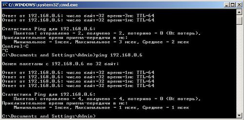
Well, go look at the result:

If we do not ping, we check the cable, the program code, and if it’s really bad, we go to our friends, we take an oscillograph and debass.
Continued in the following articles.
I thank my friends for the help in creating the device and the article.
The developed device repeats something IRemo: Tap , as well as some other analogues, which was already written on habrahabr. My version will be simpler and cheaper. For communications, I chose the usual twisted pair, and to control the device will have its own web page.
This article describes the first stage - the creation of "brains" for the future project.
So stage number zero
It is always easier to break the development of complex things into simple "bricks". This is called the scientific principle of modularity. So for a start we will think, and we will break our idea into blocks. Globally, in the entire instrument, I identified 3 main modules: a control unit, a switching unit, and a power supply unit.
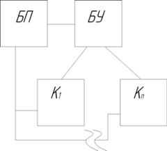
This article focuses on the control unit, which will work as a web server, as well as receive and process web forms with requests. And now we sit down and draw a block diagram of the developed module over a cup of cola:
Decoding notation is as follows:
- Power supply unit,
- Control unit,
- Kn n-th switching node (our device realizes only switching off and inclusion of light).
')
The first brick.
First stage.
Development of the first brick we begin with the choice of the element base. After familiarizing myself with the microcircuits available on the territory of Ukraine, I chose the C8051F340-GQR microcontroller (64kb flash, 4kb RAM, 10-bit ADC, a crossbar allowing to configure the UART, ADC and SPI to any processor ports, USB, 48 MHz clock frequency from the built-in source, temperature sensor) as a “brain” of the project and the CP2200-GQR chip as an ezernet controller, which will provide us with a speed of up to 10 Mbps (which is enough for us with our head). Both ICs exist in TQFP-48 packages for surface mounting. More detailed specifications in datasheets C8051F340 and CP2200 .
Of the remaining components, in the first stage, we need an Ethernet connector with a 1: 1 transformer, preferably integrated into the connector itself. I chose HR911105A.
Second phase.
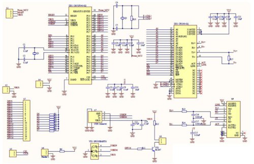
Excellent microcircuits are mined (the controller had to run for an ezernet, there is an analogue of the CP2201 but it is in the QFN-28 package, and it is a bit difficult to solder it). At this stage we will create a schematic diagram.
Here is what I got (clickable image):
Now some explanations:
- Let's start with connections mk and CP2200. The situation is greatly simplified due to the presence of an EMIF (External Memory Interface) interface on board for both microcircuits, because in fact the CP2200 is a heaped memory. Byte P3 transmits the address, byte P4-data, also bits P1.7 \ not WR when set to 0, the microchip understands what we write to it at the specified address, and when setting the bit P1.6 \ not RD reads accordingly. The connection is taken from the datasheet; also the R1-8 resistors are small enough and have a nominal value of 1 KΩ, and pull up the pins to the value of a logical unit. Their presence is not required.
Other pins:- P0.2 \ INT-clocking signal, after setting to 1 IC will begin processing our request
- P0.0 \ RES reset signal
- P0.1 \ CS-chip selection, as it turned out later, could also not be diluted.
- Also pay attention to the quartz resonator Q2; it has a nominal value of 20.000 MHz, its presence is obligatory (Q1 can be omitted).
- With the connection of the ethernet connector, too, there are no difficulties, the entire connection is also taken from the datasheet. R14, R14, C16, C17 low pass filter (face values are listed at the bottom of the article).
- I also did not forget about yusb. By closing X1.1 and X1.2 you can get power from your own using the internal voltage regulator mic, but alas, you will not provide power to the CP2200 chip (the output current is up to 100mA, the requirements of CP2200 are up to 122mA during transmission).
- A LED is connected to X6, which simply glows and signals the presence of power, a transistor switch based on the BC847 transistor, a control pin P2.7 is connected to X8, you can connect an LED here. It helped a lot when debugging firmware.
- At X4, 3.3V is supplied. On X2, you can also apply 5V for powering different flash drives and other devices in the mode when the master mode. X3 ports programmer C2. The remaining pins are connected to connector X5.
The third stage.
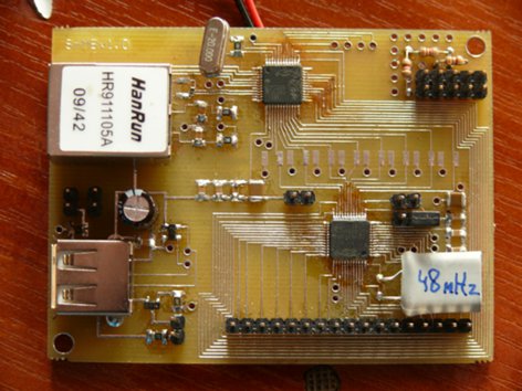
Created a schematic diagram divorced. There should be no problems. Since I printed the boards at the factory ( DNVP Elektronmash ), I chose the scheme from 2 sides (the upper right corner remained empty, so I drilled holes there, it turned out a sort of piece of the breadboard).
Well, and then we export everything to the Gerber format (the drawing of the board, each side is in its own file), the holes are saved in the NC drill format.
Get paid, collect:
Top:
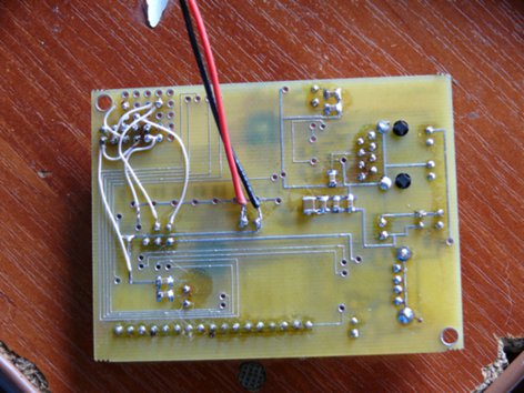
Bottom:
The abundance of wires is due to the fact that I did not know what programmer would be used, it was supposed to initially supply power and data from the programmer, but alas, I made a couple of errors when setting up the programmer and it did not work. Therefore, it was brought to the connector used (at the same time, the model part was useful).
Fourth stage.
Without a description of all the parts, I’ll not give the firmware code yet, but we’ll flash there a standard example from Silabs. There is only one problem; all the examples are sharpened for the Silbov debugging module, with the prefix CP2200DK. The differences here are only in the control pins, so open the file main.c
We are looking for the function void PORT_Init (void) change its code to:
void PORT_Init (void) { IT01CF = 0x02; // Enable Interrupt 0 on P0.3 TCON &= ~0x01; // Make /INT0 level triggered XBR1 = 0x40; // Enable crossbar and enable // weak pull-ups P0MDOUT |= 0x10 | 0x1F; // enable UTX as push-pull output P1MDOUT |= 0xD8 | 0xFF; // /WR and /RD are push-pull P2MDOUT |= 0xFF; P3MDOUT |= 0xFF; P4MDOUT |= 0xFF; } Find the function void ether_reset_low () change to:
void ether_reset_low() { P0 &= ~0x01; // Pull reset low } We do the same with void ether_reset_high ():
void ether_reset_high (void) { P0 |= 0x01; // Allow /RST to rise while(!(P0 & 0x01)); // Wait for /RST to go high } Open mn_userconst.h
install ip address:
#define IP_SRC_ADDR { 192, 168, 0, 6 } in void main ()
after port_init ();
add
P0 &= ~0x02;//Cs=0 Next, go to VFILE_DIR
rule index.html
We execute update.bat.
Thus, a standard array of hex values will be made from index.html.
Compile, collect into a hex file, assign a computer an ip address on the same network and flash it.
Pinging:
Well, go look at the result:
If we do not ping, we check the cable, the program code, and if it’s really bad, we go to our friends, we take an oscillograph and debass.
References:
- A reworked example, as well as drawings of the board of altium format (10th version) and a list of elements in pdf format:
- Datasheets (technical documentation):
Continued in the following articles.
I thank my friends for the help in creating the device and the article.
Source: https://habr.com/ru/post/124268/
All Articles