STM32F1xx - we treat arduine dependence together
Good afternoon, dear habrovchane!
After a long break associated with the protection of a graduation project in Baumanka, I again returned to writing articles. Since recently, I started 32-bit microcontrollers of the STM32F series on the ARM Cortex-M3 core, this will be my story. The article will help me to systematize knowledge about these wonderful microcontrollers, and I hope that you will serve as one of the steps towards their use and dispel fears and doubts that always arise after the cozy 8-bit AVRok when mentioning the terrible 32-bit monsters.
So why Cortex, what are bad avr?
Generally speaking, nothing. Microcontrollers from the AVR family are very convenient, low consuming and easy to learn. But this is where some peculiarity lies - starting out with AVR, it’s hard for a person to force himself to switch to a more complex architecture. It would seem that everything works so well, but it does not work - so I will take AVRku more. More. Anyway, do not climb? I will take two AVRki, I will build whatnot from Arduino, until all that I planned does not fit into the chip. This is the wrong approach. Most often this is manifested in those who are engaged in electronics "for themselves." I can not say that it’s just really disgusting and you should break arduins with hammers, but if you want to go beyond the crafts on your knee or take your hobby to a new level, you should objectively evaluate the areas of application of microcontrollers. By the way, the manufacturers of microcontrollers on ARM Cortex-M3 are calling for active actions; they are ready to send a new debugging to ARM for the video of your old debug board being destroyed on an 8-bit controller, however, we will try to do without vandalism.
So, moving on to specific examples. Younger models of the STM32F10x family can be purchased at a price of 30p per piece. As you can see, the price is comparable with AVRs. For this price, you will receive a 32-bit microcontroller rated at 24 MHz with a Flash and RAM volume similar to that of the ATMega88. Older models can be clocked with a frequency of up to 72 MHz, the volume of flash / RAM reaches 1M / 128K. When should I use it instead of megu? Then, when you run into the “ceiling” of the AVR. Such a “ceiling” is usually computing tasks (signal processing, in particular). Yes, I know, if you wish, you can try and shove DSP algorithms in mega, for training purposes this is even useful. But in a real device it is much more appropriate to use a suitable processor. What do we get by choosing STM?
We now turn to the disadvantages. I can mark two:
What can be concluded? Very simple: try to always think with your head, and objectively assess the situation, not allowing your mind to overshadow the habits and attachments to specific architectures. If you see that it would be nice to use 16-bit (and higher) data, count filters, send large amounts of information - do not grab hold of arduin bookshelves. At the same time, if you just need to check the value of the light sensor just once a minute and cut in the desk lamp, then you shouldn’t immediately run after the cortex.
We now turn to more pressing issues. What do we need to start working with the STM32F?
Contrary to the opinions of some comrades, 300r will be enough for you. For the purchase of such a debug board here: STM32VLDISCOVERY
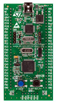
It immediately contains both a programmer and a programmable part in the form of an STM32F100RB controller on board.
Also, it does not hurt to get such a layout: WBU-206

Allows you not to be distracted by soldering, but immediately focus on your goals. True, complex circuits on it look disgusting - tight intertwining of wires can strike terror in immature minds)
')
Here, in principle, and all of the iron you need to start. Since the basics of the work were outlined in my articles by the respected DiHalt , I will not repeat myself and will consider that a project can be created in Keil, and any reader of the article can compile it and flash it. If not, we are educated on easyelectronics.ru .
In order not to be so boring to work, let's start not with the annoying LEDs, but with the servos. A servo drive is an electric motor that is included in the servo system. Feedback is implemented by obtaining information about the actual position of the shaft - say, by placing a potentiometer on one of the shafts of the gearbox.
The control system receives from us information about the angle at which we want to turn the servo shaft, from the potentiometer - on which it is now turned, and forms the control voltage on the motor windings. All this Chinese comrades upyvayut in a very small body, for example, such: Tower Pro MG90S
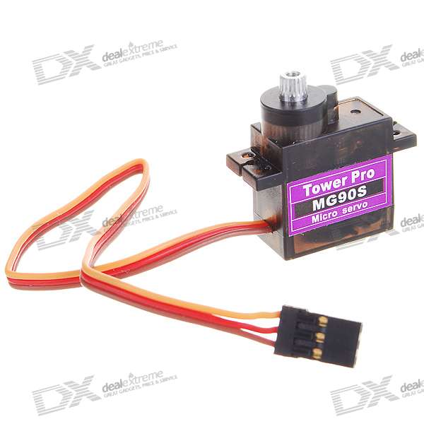
They cost less than 200 rubles, the delivery is free (true, rather long), the gearbox is metal, not plastic. Traditionally, servas are controlled by a PWM signal with a frequency of 20-60 Hz (note, hertz , not kilohertz), the signal's rotation ratio sets the angle of rotation. Specific values depend on the servo-motor itself, so we will experiment, the benefit can be to debug the firmware on the go. Unfortunately, I did not find any information directly on these motors, so I chose the values from the Futaba Japanese servos - without thinking, fortunately, the Chinese developers didn’t move much away from the standards, and the server understood it quite well. The purpose of the article will be to start a timer on STM32F1xx, generate a PWM signal with it and use this PWM to spin the Chinese server.
Turn to the gland. In this case, no special schemes are required from us - everything is already on the debug board. We just have to connect the server to it. A standard servomotor has 3 wires — ground, power, and control (usually painted black, red, and orange, respectively). For the MG90S drives I mentioned, the power supply can vary from 4.8 to 6V, and the idle consumption, according to my measurements, does not exceed 40 mA, so you can power them directly from the pin 5V of the debug board. The PWM will be served from one of the timers onboard the controller. Each timer has 4 independent PWM channels, so that it is possible without straining to turn up to 4 servos with one timer. Timers with numbers 1 and 8 are somewhat more advanced than the others - they are designed to control the drivers of field-effect transistors included in the half-bridge circuit, so we will not touch them yet (despite the fact that they can also produce simple PWM signals).
Instead, use the timer number 2, which falls into the category of General Purpose Timers. To manage the servos, it was convenient for me to use its channels 3 and 4. According to the documentation, channels 3 and 4 are connected to pins PA2 and PA3.
So, as a result, our experiment area is a STM32VLDISCOVERY debugging board connected to a computer's USB and two Tower Pro MG90S servo drives whose lands (black wire) are connected to the GND pin of the debugging board, power is connected to its pin 5B and the control wires of the first and second Serves are connected to pins PA2 and PA3 respectively. If you have an oscilloscope, you can connect its channels to PA2, PA3 to immediately observe the generated signal.
We now turn to the code.
In the code, I will focus on working with registers instead of using the Standard Peripherals Library - because IMHO should examine how it all works from the inside, before trying to abstract from iron. We will assume that creating a project for a debugging board in Keila and connecting CMSIS for you will not be difficult, it is described in detail in the article on easyelectronics ARM. Training course. Keil + CMSIS. Creating a project
So, the starting point for us will be the project in Keil uVision with the CMSIS connected:
This should all be compiled, flashed into the memory of the controller and debugged. If this does not happen - read the article mentioned on easyelectronics.
The start code from the assembler file (I call it startup_stm32f10x_md_vl.s ) contains the declaration of handwashing and exceptions that can be safely redefined in our program. It also calls the SystemInit function, defined in the CMSIS library core_cm3.h file. Some registers are configured in it, in particular, those responsible for clocking - this can all be done manually by replacing the SystemInit call in the start file with a call to its function, but for now we will not dwell on this issue. I will only note that the frequency is set in accordance with the settings in the system_stm32f10x.c file, where SYSCLK_FREQ_24MHz is equal to 24,000,000 on line 76.
The control code is very simple, however, there are several points that should be paid attention to so that you do not have to search for a problem in the code for a long time.
The first moment is mentioned DiHalt 'om - in STMs the clocking of almost all peripheral modules is disabled by default in order to save energy. So first of all we submit clocks to our periphery:
In these two lines, we set the TIM2EN bits (to feed the clock on timer 2) and IOPAEN (to feed the clock on port A) in the APB1ENR and APB2ENR registers, respectively (APB1 and APB2 Peripheral Clock Enable Register).
And here comes another important thing:
We set both pins, PA2, PA3, to the exit, but the fact is that in STMs there is a separation in the GPIO operating modes. If we want to set the pin state to 1 or 0 programmatically, then we should choose the Output push-pull or Output open drain mode. If it is supposed that some periphery of the timer type, which is specified in the datasheet for a specific controller model in the pinout section in the Alternate Functions column, will control its state, then the mode of operation should be Alternate function push-pull or Alternate function open drain. If you set the mode incorrectly, the timer will not be able to issue a PWM signal.
Briefly about the registers - each port contains two control registers CRL and CRH , in fact, absolutely identical. The CRL stores pin settings 0–7, in the CRH - 8–15. Each pin has 4 bits, two of which, MODE , are responsible for the I / O direction and the limitation on the maximum pin switching frequency in the output mode, the other two, CNF , store the same mode of operation.
All in all, this gives us eight possible pin states:
For our purposes, we need pins configured for the output controlled by the periphery in the push-pull mode. Thus, it is necessary in the CRL register to set the values of MODE2 [1: 0] and MODE3 [1: 0] to some other value than 00, say, 11, and CNF2 [1: 0] and CNF3 [1: 0] - to 10
The remaining registers related to the periphery are described in detail in document RM0008, STM32F1xx Reference Manual . In short, the IDR and ODR registers contain input and output values on the port pins, the BSRR is responsible for setting / resetting, and the BRR only for resetting bits in the ODR , and it does it atomically, that is, this operation occurs during one bus cycle and into it interruption cannot interfere. The last port register, LCKR, allows you to “lock” the pin value, not allowing it to be changed to the cut itself.
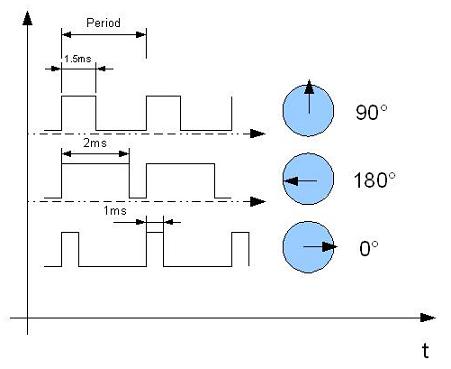
Next, set the timer. According to the data found on the Internet, the PWM period should be selected from 20 to 60 Hz, while pulses with a width of about 1 ms mean 0 degrees, 1.5 ms - 90 degrees, and 2 ms - 180.
As for the width of the PWM - in principle, you can choose any, but the positioning accuracy of the serv is still finite, so I chose 12 bits. It should also be remembered that 12 bits describe a change in pulse width from 0 ms to a value equal to its period, while the server operates on a range from 1 to 2 ms, therefore not all 12 bits will be at our disposal. Looking ahead, I will say that as a result of the experiments, I came to the following parameters:
Choosing a PWM frequency of 35 Hz and a bit width of 12 bits, we get 4096 values for the entire period, 0x50 will correspond to a width of 0.56 ms, and 0x150 will correspond to a width of 2.34 ms.
Thus, we obtain 256 values at approximately 180 degrees, which means a resolution of approximately 40 arc-minutes per sample. If desired, you can continue the experiments and determine the exact boundary values and the accuracy with which the drive can perform the positioning.
So, set the timer 2 with the following code snippet:
It's all very trivial: the PSC (Prescaler) register is responsible for the prescaler, the ARR (Auto-reload register) register for the maximum value that the timer will tick to. Putting the number 0FFF in ARR, we get a 12-bit timer, its counting period will be equal to the clock frequency divided by 0xFFF, that is, 24000000/4096 = 5859. Dividing this value by another 0xA7, we get 5859/167 = 35 Hz.
The value of the CCR3 and CCR4 (Capture Compare register) registers is compared with the value of the counter and sets the actual duty cycle of the PWM. Further we set the timer operation mode:
The situation is the same as with the port setting registers - the two setting registers Capture and Compare Mode register, CCMR1 , CCMR2 are responsible for the operation modes of channels 1,2 and 3,4, respectively. There are many settings, and it is better to read the Reference Manual on this. If the overview - registers are responsible for the modes associated with the capture of the PW signal on the timer and its output. The CCxS bits, where x is the channel number, set this channel to input or output. By default, the output mode is enabled, so we will not touch them. The set bits OCxM [2: 0] are responsible for how the channel will react to the comparison of the value of the counter (which is stored, by the way, in the register
TIM2-> CNT ) and CCRx registers. In total there are 8 options:
Set mode 110, normal PWM. Do not forget in the CCER register (Capture / compare enable register) to set the CCxE bit to enable the output of the corresponding channel.
After that, turn on the entire timer by setting the CEN bit in the CR1 register (Control Register 1).
Everything, PWM went, a beautiful picture should appear on the oscilloscope screen, and the servos should take opposite positions. If desired, you can set up a breakpoint after all initializations and change values using the built-in Keyl tool to view and edit the processor and peripheral registers, immediately observing the change in the signal's duty cycle on the oscilloscope screen and the position of the servo drive shaft.
Now let's make the program a bit more interesting for the sake of self-education - we will change the angle values from maximum to minimum. To do this, recall that the ARM Cortex-M3 core includes the so-called SysTick Timer - this is a 24-bit timer designed for global synchronization and interrupt generation, for example, when implementing an operating system. The timer is initialized using the SysTick_Config function (uint32_t Ticks) . This feature is part of CMSIS, which is more “fundamental” than the Standard Peripherals Library, so we will use it.
If you are interested in the insides of this function, you can go to its description in the depths of CMSIS (file core_cm3.h , line 1137). In general, the function does not do anything particularly complicated, it only checks the value of the parameter Ticks passed to it for exceeding 24 bits, and then sets the registers:
• SysTick-> LOAD to Ticks is the top of the timer counter, interrupts will be triggered at such intervals.
• SysTick-> VAL to 0 is the current value of the counter.
• CLKSOURCE , TICKINT , ENABLE bits in the SysTick-> CTRL register in 1.
The CLKSOURCE bit is responsible for the clock source for the timer. Generally speaking, the core specification does not describe what the second signal should be (the first one is always connected to the system clock), so the effect of this bit may vary from manufacturer to manufacturer. In STM32F, the second signal is connected to SystemCoreClock / 8. Having set the bit to 1, select the source of the system clock.
The TICKINT bit enables the generation of an interrupt (or rather, an exception) over the timer overflow. Set to 1, for the sake of it, and everything was started)
The ENABLE bit turns on the timer.
In addition to the described actions, the SysTick_Config function also sets the interrupt priority to 240, which is very low, considering that priorities start from 0 (actually from -3, but priorities less than 0 are non-configurable).
Since the current PWM settings mean 256 steps from 0 to 180 degrees, let's set the timer to the frequency
SystemCoreClock / 256, so that this serv path goes in 1 second:
The SystemCoreClock constant is defined in system_stm32f10x.c , line 114, and is equal to the number of core clock signals in 1 s, i.e., 24,000,000.
It remains to describe the timer interrupt handler and the work will be completed!
Since we have two channels, we will write a handler with the expectation of both channels at once. Since we have the same memory space, we can freely access registers as ordinary memory cells, so we immediately declare a pointer to two registers:
Then everything is very simple - we organize a cycle through two channels, add or subtract 1 from the current value of the duty cycle (depending on the direction) and, when the servo reaches the extreme position, change directions.
Everything, we compile, and if everything is done correctly, then we enjoy the spectacle of the kind that is presented by me on the video below.
The complete project code looks like this:
On this I have everything. If you are interested in this topic, in the following articles I will try to consider something more interesting, for example, working with a display from a mobile phone.
UPD:
In order not to go far, useful links:
After a long break associated with the protection of a graduation project in Baumanka, I again returned to writing articles. Since recently, I started 32-bit microcontrollers of the STM32F series on the ARM Cortex-M3 core, this will be my story. The article will help me to systematize knowledge about these wonderful microcontrollers, and I hope that you will serve as one of the steps towards their use and dispel fears and doubts that always arise after the cozy 8-bit AVRok when mentioning the terrible 32-bit monsters.
So why Cortex, what are bad avr?
Ceiling
Generally speaking, nothing. Microcontrollers from the AVR family are very convenient, low consuming and easy to learn. But this is where some peculiarity lies - starting out with AVR, it’s hard for a person to force himself to switch to a more complex architecture. It would seem that everything works so well, but it does not work - so I will take AVRku more. More. Anyway, do not climb? I will take two AVRki, I will build whatnot from Arduino, until all that I planned does not fit into the chip. This is the wrong approach. Most often this is manifested in those who are engaged in electronics "for themselves." I can not say that it’s just really disgusting and you should break arduins with hammers, but if you want to go beyond the crafts on your knee or take your hobby to a new level, you should objectively evaluate the areas of application of microcontrollers. By the way, the manufacturers of microcontrollers on ARM Cortex-M3 are calling for active actions; they are ready to send a new debugging to ARM for the video of your old debug board being destroyed on an 8-bit controller, however, we will try to do without vandalism.
So, moving on to specific examples. Younger models of the STM32F10x family can be purchased at a price of 30p per piece. As you can see, the price is comparable with AVRs. For this price, you will receive a 32-bit microcontroller rated at 24 MHz with a Flash and RAM volume similar to that of the ATMega88. Older models can be clocked with a frequency of up to 72 MHz, the volume of flash / RAM reaches 1M / 128K. When should I use it instead of megu? Then, when you run into the “ceiling” of the AVR. Such a “ceiling” is usually computing tasks (signal processing, in particular). Yes, I know, if you wish, you can try and shove DSP algorithms in mega, for training purposes this is even useful. But in a real device it is much more appropriate to use a suitable processor. What do we get by choosing STM?
- Full 32-bit computing. You do not have to spend precious cycles on the work of data, bit depth of more than 8 bits, the ALU will do it for you.
- DMA. The DMA controller for AVR users is a luxury, available only in older, monstrous models. In STM32F1xx DMA is even in the youngest crystals. Using it, you can easily and naturally transfer data blocks between peripherals and memory without using a processor. It is very useful when working with memory cards, sending large amounts of data on all kinds of UARTs and their ilk, organizing audio capture from the ADC and outputting data to a DAC.
- Speaking of DAC - in most models, including the younger ones, there is a 12-bit DAC. For music lovers it will not work, but it is convenient to output any debug analog info. Yes, and all sorts of toys with sound do more convenient than with the PWM.
- NVIC, I mean Nested Vector Interrupt Controller, is a programmable interrupt controller that allows you to assign priorities to them and guaranteeing a constant time to enter the interrupt is a necessary thing for systems with real-time restrictions.
- A nice little thing like an SD card controller. The SPI controller on STMs contains a hardware CRC calculator, it can be used to fully communicate with SD cards.
- Availability of some DSP commands. Truth be told, the Cortex-M3 is not exactly a DSP core, but such a processor is often required — not TI's monster-eating monsters, but not weak AVRs. The presence of a 32x32 hardware multiplier and multiplication with accumulation will help in processing the signal on M3.
- More advanced models have a USB controller, and flash volumes reach a megabyte, while you can still choose the case yourself - STM are pin-compatible and even older models can be bought in a 64-foot case. Fee rerun will not have to.
We now turn to the disadvantages. I can mark two:
- The cabinets of the STM32F1xx are much less accessible at home than those of the same AVR. The board will succeed, but it will require some skill.
- The architecture of these controllers is very complicated, for one timer it is necessary to have 12 registers (they are also 32-bit!), So it will not be possible to master the evening, you will have to deal with them purposefully.
What can be concluded? Very simple: try to always think with your head, and objectively assess the situation, not allowing your mind to overshadow the habits and attachments to specific architectures. If you see that it would be nice to use 16-bit (and higher) data, count filters, send large amounts of information - do not grab hold of arduin bookshelves. At the same time, if you just need to check the value of the light sensor just once a minute and cut in the desk lamp, then you shouldn’t immediately run after the cortex.
We now turn to more pressing issues. What do we need to start working with the STM32F?
Getting Started with STM32F1xx
Contrary to the opinions of some comrades, 300r will be enough for you. For the purchase of such a debug board here: STM32VLDISCOVERY
It immediately contains both a programmer and a programmable part in the form of an STM32F100RB controller on board.
Also, it does not hurt to get such a layout: WBU-206
Allows you not to be distracted by soldering, but immediately focus on your goals. True, complex circuits on it look disgusting - tight intertwining of wires can strike terror in immature minds)
')
Here, in principle, and all of the iron you need to start. Since the basics of the work were outlined in my articles by the respected DiHalt , I will not repeat myself and will consider that a project can be created in Keil, and any reader of the article can compile it and flash it. If not, we are educated on easyelectronics.ru .
In order not to be so boring to work, let's start not with the annoying LEDs, but with the servos. A servo drive is an electric motor that is included in the servo system. Feedback is implemented by obtaining information about the actual position of the shaft - say, by placing a potentiometer on one of the shafts of the gearbox.
The control system receives from us information about the angle at which we want to turn the servo shaft, from the potentiometer - on which it is now turned, and forms the control voltage on the motor windings. All this Chinese comrades upyvayut in a very small body, for example, such: Tower Pro MG90S
They cost less than 200 rubles, the delivery is free (true, rather long), the gearbox is metal, not plastic. Traditionally, servas are controlled by a PWM signal with a frequency of 20-60 Hz (note, hertz , not kilohertz), the signal's rotation ratio sets the angle of rotation. Specific values depend on the servo-motor itself, so we will experiment, the benefit can be to debug the firmware on the go. Unfortunately, I did not find any information directly on these motors, so I chose the values from the Futaba Japanese servos - without thinking, fortunately, the Chinese developers didn’t move much away from the standards, and the server understood it quite well. The purpose of the article will be to start a timer on STM32F1xx, generate a PWM signal with it and use this PWM to spin the Chinese server.
Turn to the gland. In this case, no special schemes are required from us - everything is already on the debug board. We just have to connect the server to it. A standard servomotor has 3 wires — ground, power, and control (usually painted black, red, and orange, respectively). For the MG90S drives I mentioned, the power supply can vary from 4.8 to 6V, and the idle consumption, according to my measurements, does not exceed 40 mA, so you can power them directly from the pin 5V of the debug board. The PWM will be served from one of the timers onboard the controller. Each timer has 4 independent PWM channels, so that it is possible without straining to turn up to 4 servos with one timer. Timers with numbers 1 and 8 are somewhat more advanced than the others - they are designed to control the drivers of field-effect transistors included in the half-bridge circuit, so we will not touch them yet (despite the fact that they can also produce simple PWM signals).
Instead, use the timer number 2, which falls into the category of General Purpose Timers. To manage the servos, it was convenient for me to use its channels 3 and 4. According to the documentation, channels 3 and 4 are connected to pins PA2 and PA3.
So, as a result, our experiment area is a STM32VLDISCOVERY debugging board connected to a computer's USB and two Tower Pro MG90S servo drives whose lands (black wire) are connected to the GND pin of the debugging board, power is connected to its pin 5B and the control wires of the first and second Serves are connected to pins PA2 and PA3 respectively. If you have an oscilloscope, you can connect its channels to PA2, PA3 to immediately observe the generated signal.
We now turn to the code.
Software part
In the code, I will focus on working with registers instead of using the Standard Peripherals Library - because IMHO should examine how it all works from the inside, before trying to abstract from iron. We will assume that creating a project for a debugging board in Keila and connecting CMSIS for you will not be difficult, it is described in detail in the article on easyelectronics ARM. Training course. Keil + CMSIS. Creating a project
So, the starting point for us will be the project in Keil uVision with the CMSIS connected:
#include "stm32f10x.h" int main() { while(1); } This should all be compiled, flashed into the memory of the controller and debugged. If this does not happen - read the article mentioned on easyelectronics.
The start code from the assembler file (I call it startup_stm32f10x_md_vl.s ) contains the declaration of handwashing and exceptions that can be safely redefined in our program. It also calls the SystemInit function, defined in the CMSIS library core_cm3.h file. Some registers are configured in it, in particular, those responsible for clocking - this can all be done manually by replacing the SystemInit call in the start file with a call to its function, but for now we will not dwell on this issue. I will only note that the frequency is set in accordance with the settings in the system_stm32f10x.c file, where SYSCLK_FREQ_24MHz is equal to 24,000,000 on line 76.
The control code is very simple, however, there are several points that should be paid attention to so that you do not have to search for a problem in the code for a long time.
The first moment is mentioned DiHalt 'om - in STMs the clocking of almost all peripheral modules is disabled by default in order to save energy. So first of all we submit clocks to our periphery:
RCC->APB1ENR|= RCC_APB1ENR_TIM2EN; RCC->APB2ENR|= RCC_APB2ENR_IOPAEN; In these two lines, we set the TIM2EN bits (to feed the clock on timer 2) and IOPAEN (to feed the clock on port A) in the APB1ENR and APB2ENR registers, respectively (APB1 and APB2 Peripheral Clock Enable Register).
And here comes another important thing:
GPIOA->CRL |=GPIO_CRL_MODE2; GPIOA->CRL &=~GPIO_CRL_CNF2_0; GPIOA->CRL |=GPIO_CRL_CNF2_1; GPIOA->CRL |=GPIO_CRL_MODE3; GPIOA->CRL &=~GPIO_CRL_CNF3_0; GPIOA->CRL |=GPIO_CRL_CNF3_1; We set both pins, PA2, PA3, to the exit, but the fact is that in STMs there is a separation in the GPIO operating modes. If we want to set the pin state to 1 or 0 programmatically, then we should choose the Output push-pull or Output open drain mode. If it is supposed that some periphery of the timer type, which is specified in the datasheet for a specific controller model in the pinout section in the Alternate Functions column, will control its state, then the mode of operation should be Alternate function push-pull or Alternate function open drain. If you set the mode incorrectly, the timer will not be able to issue a PWM signal.
Briefly about the registers - each port contains two control registers CRL and CRH , in fact, absolutely identical. The CRL stores pin settings 0–7, in the CRH - 8–15. Each pin has 4 bits, two of which, MODE , are responsible for the I / O direction and the limitation on the maximum pin switching frequency in the output mode, the other two, CNF , store the same mode of operation.
All in all, this gives us eight possible pin states:
- Input not pulled ( MODE [1: 0] = 00, CNF [1: 0] = 01)
- Input pulled to power ( MODE [1: 0] = 00, CNF [1: 0] = 10, 1 is output to the port)
- Input pulled to the ground ( MODE [1: 0] = 00, CNF [1: 0] = 10, 0 output at the port output)
- Analog input ( MODE [1: 0] = 00, CNF [1: 0] = 00) - this switches off the Schmitt trigger and pull-up resistors, the pin changes to the Z-state.
- Output, open drain GPIO ( MODE [1: 0]! = 00, CNF [1: 0] = 01)
- Out, push-pull GPIO ( MODE [1: 0]! = 00, CNF [1: 0] = 00)
- Output, open drain controlled by peripherals ( MODE [1: 0]! = 00, CNF [1: 0] = 11)
- Out, push-pull managed by peripherals ( MODE [1: 0]! = 00, CNF [1: 0] = 10)
For our purposes, we need pins configured for the output controlled by the periphery in the push-pull mode. Thus, it is necessary in the CRL register to set the values of MODE2 [1: 0] and MODE3 [1: 0] to some other value than 00, say, 11, and CNF2 [1: 0] and CNF3 [1: 0] - to 10
The remaining registers related to the periphery are described in detail in document RM0008, STM32F1xx Reference Manual . In short, the IDR and ODR registers contain input and output values on the port pins, the BSRR is responsible for setting / resetting, and the BRR only for resetting bits in the ODR , and it does it atomically, that is, this operation occurs during one bus cycle and into it interruption cannot interfere. The last port register, LCKR, allows you to “lock” the pin value, not allowing it to be changed to the cut itself.
Next, set the timer. According to the data found on the Internet, the PWM period should be selected from 20 to 60 Hz, while pulses with a width of about 1 ms mean 0 degrees, 1.5 ms - 90 degrees, and 2 ms - 180.
As for the width of the PWM - in principle, you can choose any, but the positioning accuracy of the serv is still finite, so I chose 12 bits. It should also be remembered that 12 bits describe a change in pulse width from 0 ms to a value equal to its period, while the server operates on a range from 1 to 2 ms, therefore not all 12 bits will be at our disposal. Looking ahead, I will say that as a result of the experiments, I came to the following parameters:
- PWM signal frequency: 35 Hz. I chose just as an average value, the server works stably at both 30 and 50 Hz.
- The pulse width corresponding to 0 degrees: about 0.5 ms, however, if you select it to be 0.5 or less, the server starts to crack, because is on the border of their physical abilities in turn. Therefore, for a more stable operation, I use pulses about 0.56 ms wide
- The pulse width, corresponding to 180 degrees: about 2.3 ms, the same situation as with zero rotation - if you set a little more than the boundary, it starts to pop.
Choosing a PWM frequency of 35 Hz and a bit width of 12 bits, we get 4096 values for the entire period, 0x50 will correspond to a width of 0.56 ms, and 0x150 will correspond to a width of 2.34 ms.
Thus, we obtain 256 values at approximately 180 degrees, which means a resolution of approximately 40 arc-minutes per sample. If desired, you can continue the experiments and determine the exact boundary values and the accuracy with which the drive can perform the positioning.
So, set the timer 2 with the following code snippet:
TIM2->PSC = 0x00A7; TIM2->ARR = 0x0FFF; TIM2->CCR3 = 0x050; TIM2->CCR4 = 0x0150; It's all very trivial: the PSC (Prescaler) register is responsible for the prescaler, the ARR (Auto-reload register) register for the maximum value that the timer will tick to. Putting the number 0FFF in ARR, we get a 12-bit timer, its counting period will be equal to the clock frequency divided by 0xFFF, that is, 24000000/4096 = 5859. Dividing this value by another 0xA7, we get 5859/167 = 35 Hz.
The value of the CCR3 and CCR4 (Capture Compare register) registers is compared with the value of the counter and sets the actual duty cycle of the PWM. Further we set the timer operation mode:
TIM2->CCMR2 |= TIM_CCMR2_OC3M_1|TIM_CCMR2_OC3M_2; TIM2->CCER |= TIM_CCER_CC3E; TIM2->CCMR2 |= TIM_CCMR2_OC4M_1|TIM_CCMR2_OC4M_2; TIM2->CCER |= TIM_CCER_CC4E; TIM2->CR1 |= TIM_CR1_CEN; The situation is the same as with the port setting registers - the two setting registers Capture and Compare Mode register, CCMR1 , CCMR2 are responsible for the operation modes of channels 1,2 and 3,4, respectively. There are many settings, and it is better to read the Reference Manual on this. If the overview - registers are responsible for the modes associated with the capture of the PW signal on the timer and its output. The CCxS bits, where x is the channel number, set this channel to input or output. By default, the output mode is enabled, so we will not touch them. The set bits OCxM [2: 0] are responsible for how the channel will react to the comparison of the value of the counter (which is stored, by the way, in the register
TIM2-> CNT ) and CCRx registers. In total there are 8 options:
- 000 - the comparison does not affect the output
- 001 - if the values at the channel output match, then 1 is set
- 010 - if the values at the channel output match, then 0 is set.
- 011 - if the values match, the output signal switches to the opposite state
- 100 - output is always set to 0
- 101 - output is always set to 1
- 110 - PWM, mode 1, normal (as long as the value in CCRx < CNT , at output 1, otherwise 0)
- 111 - PWM, mode 2, inverse (as long as the value is in CCRx < CNT , at output 0, otherwise 1)
Set mode 110, normal PWM. Do not forget in the CCER register (Capture / compare enable register) to set the CCxE bit to enable the output of the corresponding channel.
After that, turn on the entire timer by setting the CEN bit in the CR1 register (Control Register 1).
Everything, PWM went, a beautiful picture should appear on the oscilloscope screen, and the servos should take opposite positions. If desired, you can set up a breakpoint after all initializations and change values using the built-in Keyl tool to view and edit the processor and peripheral registers, immediately observing the change in the signal's duty cycle on the oscilloscope screen and the position of the servo drive shaft.
Now let's make the program a bit more interesting for the sake of self-education - we will change the angle values from maximum to minimum. To do this, recall that the ARM Cortex-M3 core includes the so-called SysTick Timer - this is a 24-bit timer designed for global synchronization and interrupt generation, for example, when implementing an operating system. The timer is initialized using the SysTick_Config function (uint32_t Ticks) . This feature is part of CMSIS, which is more “fundamental” than the Standard Peripherals Library, so we will use it.
If you are interested in the insides of this function, you can go to its description in the depths of CMSIS (file core_cm3.h , line 1137). In general, the function does not do anything particularly complicated, it only checks the value of the parameter Ticks passed to it for exceeding 24 bits, and then sets the registers:
• SysTick-> LOAD to Ticks is the top of the timer counter, interrupts will be triggered at such intervals.
• SysTick-> VAL to 0 is the current value of the counter.
• CLKSOURCE , TICKINT , ENABLE bits in the SysTick-> CTRL register in 1.
The CLKSOURCE bit is responsible for the clock source for the timer. Generally speaking, the core specification does not describe what the second signal should be (the first one is always connected to the system clock), so the effect of this bit may vary from manufacturer to manufacturer. In STM32F, the second signal is connected to SystemCoreClock / 8. Having set the bit to 1, select the source of the system clock.
The TICKINT bit enables the generation of an interrupt (or rather, an exception) over the timer overflow. Set to 1, for the sake of it, and everything was started)
The ENABLE bit turns on the timer.
In addition to the described actions, the SysTick_Config function also sets the interrupt priority to 240, which is very low, considering that priorities start from 0 (actually from -3, but priorities less than 0 are non-configurable).
Since the current PWM settings mean 256 steps from 0 to 180 degrees, let's set the timer to the frequency
SystemCoreClock / 256, so that this serv path goes in 1 second:
SysTick_Config(SystemCoreClock/256); The SystemCoreClock constant is defined in system_stm32f10x.c , line 114, and is equal to the number of core clock signals in 1 s, i.e., 24,000,000.
It remains to describe the timer interrupt handler and the work will be completed!
int8_t ChannelDir[2]={1,-1}; volatile uint16_t *DutyCycle[2]={TIM2->CCR3,&TIM2->CCR4}; void SysTick_Handler() { uint8_t i; for(i=0;i<2;i++) { *DutyCycle[i]+=ChannelDir[i]; if(*DutyCycle[i]<0x50) ChannelDir[i]=1; if(*DutyCycle[i]>0x150) ChannelDir[i]=-1; } } Since we have two channels, we will write a handler with the expectation of both channels at once. Since we have the same memory space, we can freely access registers as ordinary memory cells, so we immediately declare a pointer to two registers:
volatile uint16_t *DutyCycle[2]={&TIM2->CCR3,&TIM2->CCR4}; Then everything is very simple - we organize a cycle through two channels, add or subtract 1 from the current value of the duty cycle (depending on the direction) and, when the servo reaches the extreme position, change directions.
Everything, we compile, and if everything is done correctly, then we enjoy the spectacle of the kind that is presented by me on the video below.
The complete project code looks like this:
#include "stm32f10x.h" int8_t ChannelDir[2]={1,-1}; volatile uint16_t *DutyCycle[2]={&TIM2->CCR3,&TIM2->CCR4}; void SysTick_Handler() { uint8_t i; for(i=0;i<2;i++) { *DutyCycle[i]+=ChannelDir[i]; if(*DutyCycle[i]<0x50) ChannelDir[i]=1; if(*DutyCycle[i]>0x150) ChannelDir[i]=-1; } } int main() { RCC->APB2ENR |= RCC_APB2ENR_IOPAEN; RCC->APB1ENR |= RCC_APB1ENR_TIM2EN; GPIOA->CRL |=GPIO_CRL_MODE2; GPIOA->CRL &=~GPIO_CRL_CNF2_0; GPIOA->CRL |=GPIO_CRL_CNF2_1; GPIOA->CRL |=GPIO_CRL_MODE3; GPIOA->CRL &=~GPIO_CRL_CNF3_0; GPIOA->CRL |=GPIO_CRL_CNF3_1; TIM2->PSC = 0x00A7; TIM2->ARR = 0x0FFF; TIM2->CCR3 = 0x050; TIM2->CCR4 = 0x0150; TIM2->CCMR2 |= TIM_CCMR2_OC3M_1|TIM_CCMR2_OC3M_2; TIM2->CCER |= TIM_CCER_CC3E; TIM2->CCMR2 |= TIM_CCMR2_OC4M_1|TIM_CCMR2_OC4M_2; TIM2->CCER |= TIM_CCER_CC4E; TIM2->CR1 |= TIM_CR1_CEN; SysTick_Config(SystemCoreClock/256); while(1); } On this I have everything. If you are interested in this topic, in the following articles I will try to consider something more interesting, for example, working with a display from a mobile phone.
UPD:
In order not to go far, useful links:
Source: https://habr.com/ru/post/123791/
All Articles