Alteration of the D-link DIR-620 router in Zyxel Keenetic or making candy from the city
What is the D-link DIR-620 and what is Zyxel Keenetic , and why do you need to redo one into the other?
Enough to read the topic on the DIR-620 on the trunk or on the home site D-link , to understand what's what. Having a good element base (Ralink 3052 2T2R chip at 300Mbps, 32MB RAM and 8MB Flash, USB port), the router was pumped up in the software - most of the angry reviews refer specifically to the firmware. Although, what else to want from the device for $ 54, positioned for the public sector. However, Zyxel Keenetic is built on the same element base, but differs both in the price of $ 105 and in software. Declared support for USB drives, 3G and 4G modems, torrent client transmission right in the router, and it all really works. Is it possible to make Keenetic from the DIR-620? It turned out that you can.
Alteration consists of two parts: firmware and hardware improvements.
For the firmware you will need to connect to the serial port inside the router. That is, in any case, the device will have to open, losing the warranty.
However, looking ahead, I will say that the result is worth it.
')
Update as of September 25, 2011
In fairness, it is worth noting that the user deadc0de developed another method of flashing to keenetic without soldering and opening the device, which is to upload a modified firmware. Therefore, the method described in this article has become irrelevant. However, it can be considered as alternative, or emergency, when the device is no longer accessible over the network.
We make cable for connection to the serial port of the router. I used a ready-made MA-8720P cable from Siemens Cell.
Here is the cable:

Concurrently, used in the repair of drives Seagate through the technological connector.
Anyone with 3.3V levels is suitable. We solder a piece of the connector to the cable, for example, from the loop for the flop. We disassemble the router and see that the DIR-620 serial port is not decoupled, there are only a few fingers, so we solder the pins there for easy connection. Here is a picture with pin assignments (click to enlarge):
Download program TFTP32 - this is a free tftp server for windows. Download the firmware from Keenetic . Unpack and rename the file to a.bin for convenience. Install TFTP32 and put the a.bin file in the server's tftp root directory.
We register the IP address 10.10.10.3 and the mask 255.255.255.0 in our computer (however, you can leave the one that is already registered, then you will need to enter it with the firmware). We start TFTP32, we start HyperTerminal (for Windows 7, we have to use Putty ), specify the port where our cable is connected, set the connection parameters: speed 57600 , parity 8N1 , flow control disabled. Connect the router to our cable and turn on the power.
If the circuit is assembled correctly, we see it on the terminal screen:
For the firmware, you need to enter the write mode, in our case this is item 2: Load system code then write to Flash via TFTP. The main thing here is not to miss the moment, since the choice is given only 3 seconds. If the first time did not work, you will have to restart the router again.
It is assumed that the router has the address 10.10.10.123, the server tftp has the address 10.10.10.3 (we registered in the previous step. If you left your address, enter it, and assign any free router to the router
from the same subnet). The firmware will be loaded, the contents of the flash drive will be erased, the new firmware will be uploaded. All this will be seen on the terminal screen. After the firmware, the router will reboot:
Just in case, reset the router settings by long pressing Reset. After the reboot, it will have the address 192.168.1.1, login: admin, password 1234. Therefore, we prescribe an IP address from this range or enable automatic retrieval of the IP address (the router already has a DHCP server enabled).
The router is already working by cable. We go to the browser at 192.168.1.1 and get into the Zyxel Keenetic interface, rejoice at the new features in the form of support for USB flash drives, printers, modems, etc. Only bad luck, the Wi-fi module is turned off, as there is a small wireless module switch in the original Zyxel Keenetic, and it is missing in the DIR-620.
You can find out about non-working Wi-fi in the Web Interface Monitor tab: “Wireless Wi-Fi is turned off by the toggle switch on the case”.
Technical information:
The router is built on the Ralink RT3052 chip, a part of its outputs can work both the input and the output, which is determined by the value of the internal registers that are programmed during the firmware download. Zyxel manufacturers have made a Wi-Fi switch that uses one of the legs of the RT3052. In the DIR-620, this same foot controls the LED.
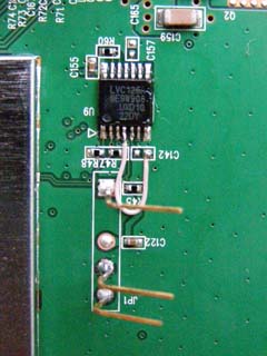
The RT3052 leg we need is connected to the 4th output of the 74lvc125a chip, to which the LEDs are connected. The 4th pin is responsible for the globe icon.
To make Wi-Fi work, you need to solder a 4.7 kΩ resistor between the track connected to the 4th leg 74lvc125a, and the power supply of 3.3 Volts. It is more convenient to do this by soldering the resistor on the back side of the board between the output of the 3.3V connector of the serial port and the pad for the uncased capacitor C259.

In order for the indicator-globe to work, we unzip the 4th leg 74lvc125a from the platform (raise it) and connect it to the common wire. It is more convenient to solder to the pad under the condenser C142.
After these actions, we get a fully functional router - the older model Zyxel Keenetic.
Written and tested on the materials of the conference ixbt . Many thanks to the user allep for the proposed method of alteration.
Enough to read the topic on the DIR-620 on the trunk or on the home site D-link , to understand what's what. Having a good element base (Ralink 3052 2T2R chip at 300Mbps, 32MB RAM and 8MB Flash, USB port), the router was pumped up in the software - most of the angry reviews refer specifically to the firmware. Although, what else to want from the device for $ 54, positioned for the public sector. However, Zyxel Keenetic is built on the same element base, but differs both in the price of $ 105 and in software. Declared support for USB drives, 3G and 4G modems, torrent client transmission right in the router, and it all really works. Is it possible to make Keenetic from the DIR-620? It turned out that you can.
Alteration consists of two parts: firmware and hardware improvements.
For the firmware you will need to connect to the serial port inside the router. That is, in any case, the device will have to open, losing the warranty.
However, looking ahead, I will say that the result is worth it.
')
Update as of September 25, 2011
In fairness, it is worth noting that the user deadc0de developed another method of flashing to keenetic without soldering and opening the device, which is to upload a modified firmware. Therefore, the method described in this article has become irrelevant. However, it can be considered as alternative, or emergency, when the device is no longer accessible over the network.
Part number 1: Firmware
We make cable for connection to the serial port of the router. I used a ready-made MA-8720P cable from Siemens Cell.
Here is the cable:
Concurrently, used in the repair of drives Seagate through the technological connector.
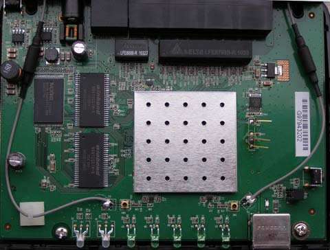
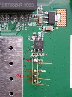
Anyone with 3.3V levels is suitable. We solder a piece of the connector to the cable, for example, from the loop for the flop. We disassemble the router and see that the DIR-620 serial port is not decoupled, there are only a few fingers, so we solder the pins there for easy connection. Here is a picture with pin assignments (click to enlarge):
Download program TFTP32 - this is a free tftp server for windows. Download the firmware from Keenetic . Unpack and rename the file to a.bin for convenience. Install TFTP32 and put the a.bin file in the server's tftp root directory.
We register the IP address 10.10.10.3 and the mask 255.255.255.0 in our computer (however, you can leave the one that is already registered, then you will need to enter it with the firmware). We start TFTP32, we start HyperTerminal (for Windows 7, we have to use Putty ), specify the port where our cable is connected, set the connection parameters: speed 57600 , parity 8N1 , flow control disabled. Connect the router to our cable and turn on the power.
If the circuit is assembled correctly, we see it on the terminal screen:
U-Boot 1.1.3 (Feb 9 2010 - 10:44:20)

Board: Ralink APSoC DRAM: 32 MB
relocate_code Pointer at: 81fb0000
flash_protect ON: from 0xBF000000 to 0xBF01D3F3
flash_protect ON: from 0xBF030000 to 0xBF030FFF
============================================
Ralink UBoot Version: 3.3
--------------------------------------------
ASIC 3052_MP2 (Port5<->None)
DRAM component: 128 Mbits SDR
DRAM bus: 32 bit
Total memory: 32 MBytes
Flash component: NOR Flash
Date:Feb 9 2010 Time:10:44:20
============================================
icache: sets:256, ways:4, linesz:32 ,total:32768
dcache: sets:128, ways:4, linesz:32 ,total:16384

##### The CPU freq = 384 MHZ ####

SDRAM bus set to 32 bit
SDRAM size =32 Mbytes

Please choose the operation:
1: Load system code to SDRAM via TFTP.
2: Load system code then write to Flash via TFTP.
3: Boot system code via Flash (default).
4: Entr boot command line interface.
9: Load Boot Loader code then write to Flash via TFTP.
For the firmware, you need to enter the write mode, in our case this is item 2: Load system code then write to Flash via TFTP. The main thing here is not to miss the moment, since the choice is given only 3 seconds. If the first time did not work, you will have to restart the router again.
2: System Load Linux Kernel then write to Flash via TFTP.
Warning!! Erase Linux in Flash then burn new one. Are you sure?(Y/N) - Y
Please Input new ones /or Ctrl-C to discard
Input device IP (10.10.10.123) ==:10.10.10.123 - ENTER
Input server IP (10.10.10.3) ==:10.10.10.3 - ENTER
Input Linux Kernel filename () ==:a.bin - ENTER
It is assumed that the router has the address 10.10.10.123, the server tftp has the address 10.10.10.3 (we registered in the previous step. If you left your address, enter it, and assign any free router to the router
from the same subnet). The firmware will be loaded, the contents of the flash drive will be erased, the new firmware will be uploaded. All this will be seen on the terminal screen. After the firmware, the router will reboot:
Please press Enter to activate this console. Sending discover...
Sending discover...
Just in case, reset the router settings by long pressing Reset. After the reboot, it will have the address 192.168.1.1, login: admin, password 1234. Therefore, we prescribe an IP address from this range or enable automatic retrieval of the IP address (the router already has a DHCP server enabled).
The router is already working by cable. We go to the browser at 192.168.1.1 and get into the Zyxel Keenetic interface, rejoice at the new features in the form of support for USB flash drives, printers, modems, etc. Only bad luck, the Wi-fi module is turned off, as there is a small wireless module switch in the original Zyxel Keenetic, and it is missing in the DIR-620.
Part number 2: Finalization
You can find out about non-working Wi-fi in the Web Interface Monitor tab: “Wireless Wi-Fi is turned off by the toggle switch on the case”.
Technical information:
The router is built on the Ralink RT3052 chip, a part of its outputs can work both the input and the output, which is determined by the value of the internal registers that are programmed during the firmware download. Zyxel manufacturers have made a Wi-Fi switch that uses one of the legs of the RT3052. In the DIR-620, this same foot controls the LED.
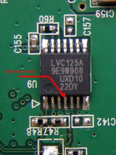
The RT3052 leg we need is connected to the 4th output of the 74lvc125a chip, to which the LEDs are connected. The 4th pin is responsible for the globe icon.
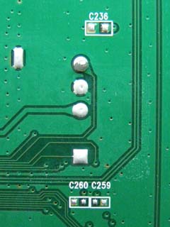
To make Wi-Fi work, you need to solder a 4.7 kΩ resistor between the track connected to the 4th leg 74lvc125a, and the power supply of 3.3 Volts. It is more convenient to do this by soldering the resistor on the back side of the board between the output of the 3.3V connector of the serial port and the pad for the uncased capacitor C259.
In order for the indicator-globe to work, we unzip the 4th leg 74lvc125a from the platform (raise it) and connect it to the common wire. It is more convenient to solder to the pad under the condenser C142.
After these actions, we get a fully functional router - the older model Zyxel Keenetic.
Written and tested on the materials of the conference ixbt . Many thanks to the user allep for the proposed method of alteration.
Source: https://habr.com/ru/post/123699/
All Articles