Overview of the SPI bus and development of the driver of the slave SPI device for embedded Linux (Part two, practical)
This is the second part of my driver development article for slave SPI devices in Linux. The previous part is here .
As mentioned above, for SPI devices there is limited support for the userspace API, with support for basic half-duplex read () and write () calls to access SPI slave devices. Using ioctl () calls, you can perform full-duplex data exchange with a slave device, as well as change device parameters.
There are a number of reasons when you may want to use this userspace API:
Of course, there are drivers that cannot be implemented by the userspace API, since they need access to other kernel interfaces (for example, interrupt handlers or other subsystems of the driver stack) that are not accessible in user space.
To enable spidev support, you must:
1. When configuring the kernel in menuconfig, activate the item:
2. Add to the array of structures spi_board_info, which was discussed in the previous paragraph, in the board file:
')
After rebuilding and loading the new kernel, the corresponding device will appear in the system with the name of the form /dev/spidevB.C, where B is the SPI bus number and C is the Chip select number. This device cannot be created manually via mknod; services such as udev / mdev should automatically create it.
Great, we have a device. It remains to learn how to work with him. Suppose we want to send byte 0x8E to a device hanging on SPI1 with CS number 2. Probably the easiest way to do this is as follows:
After that, on my test device you could observe the following picture:
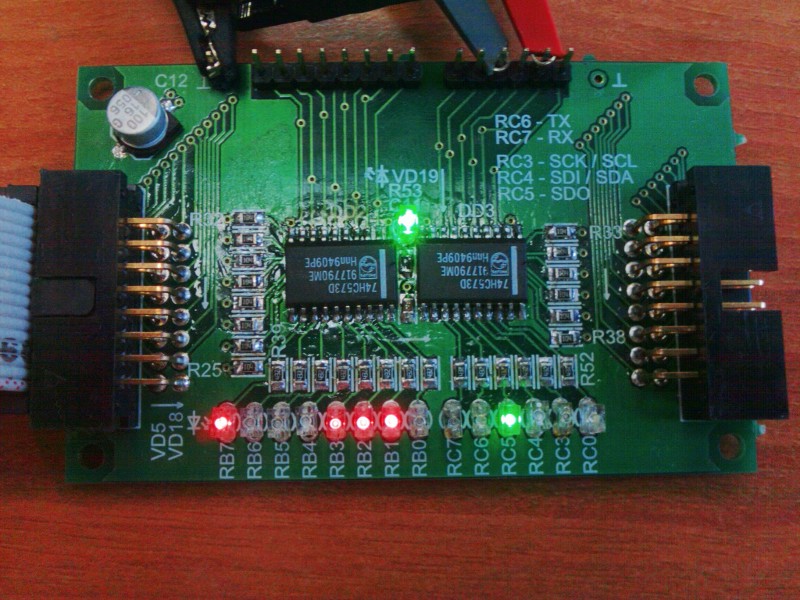
A few words should be said about the test device. Probably the most important thing is that it is almost useless and was done only to learn how to work with SPI on Linux. It is made on one shift register 74HC164N, and on the 3 elements 2I-NOT of 74HC132N some sort of chipselect is made, which only allows the clock signal at a low input level ~ CS (I want to notice right away, yes, I know about the existence of 74HC595 , but I could not get it in the city). This device has only one function - to display the last byte written to it on the LEDs. Since my device is not completely “fair”, when reading from it, we will receive not what we wrote down (as it should have been), but the value shifted one bit to the left.
Slave operation parameters can be configured via ioctl () calls. They allow you to change the data rate, the size of the transmitted word, the order of bytes in the transmission, and of course the SPI mode of operation.
The following ioctl () queries allow you to control the parameters of the slave:
By changing the frequency, I learned that my test device can operate at a frequency of no higher than about 15 MHz, which is not too bad considering the length of the cables about 25 cm, the assembly on the circuit board and the connection of contacts using MGTF.
Now I want to make one more important note, changing the order of the bits is again not supported by all controllers. In order to find out what functions the controller supports it is necessary to watch the bit mask spi_master.mode_bits. The value of the bits in the mask can be determined from the definition of flags in the spi_device structure. I will not give here full descriptions of the spi_device and spi_master structures , since they are not critically important for understanding in this case. I will give a link to the documentation in which you can find descriptions of all these structures at the end of the article.
As I mentioned at the beginning, spidev allows half-duplex transmissions using the appropriate ioctl () command:
where num is the number of transfers in the array of structures of type spi_ioc_transfer;
tr is a pointer to an array of spi_ioc_transfer structures;
In case of failure, a negative value is returned, in case of success, the total number of successfully transmitted bytes for all transmissions.
The transmission structure itself is as follows:
tx_buf and rx_buf - store pointers in user space to the buffer for sending / receiving data, respectively. If tx_buf is NULL, then zeros will be popped. If rx_buf is set to NULL, then the data received from the slave is ignored.
len is the length of the receive and transmit buffers (rx and tx) in bytes.
speed_hz - overrides the data rate for this transmission.
bits_per_word - overrides the number of bits per word for this transmission.
delay_usecs - delay in microseconds before the device is deactivated (before calling cs_deactivate), after the transfer of the last bit of data.
Almost all fields of the spi_ioc_transfer structure correspond to the fields of the spi_transfer structure. Data buffers are previously copied to / from kernel space using the copy_from_user () / copy_to_user () functions in the depths of the spidev driver.
As I said above, not all controllers support the ability to change the speed and word size for each program separately, so it’s better to put zeros there if you want to get a portable code. That is why the standard example for working with spidev in full-duplex mode, bundled with the kernel documentation, will not work on initialization of the spi_ioc_transfer structure on the at91 chips.
Remarks:
Now I will give an example, this is a simplified version of the program for working with spidev that comes with the kernel. Although this is not clearly shown in the example, but no one forbids the use of the read () and write () system calls for half-duplex data exchange.
I think everything is quite obvious here, we have already sorted out all the requests transmitted to the device via ioctl (). It remains only to bring the Makefile to build:
The only thing you need to specify your path to the cross-compiler in the variable CC.
The development of a kernel module is a much more voluminous topic, so in this case we’ll go some other way: I’ll give you a sample code first, then give a brief description of its work, explain how to use it. I will not describe all the details, otherwise no article will suffice, I will simply indicate the most important points, in the article section on the documentation you can find links to all the necessary information. In this example, I will show how to make device attributes accessible via sysfs. How to implement a driver that provides access to a device through a device file has already been discussed earlier: one , two .
My driver will provide the user with the ability to change two attributes:
value - you can write to it the number that you want to display in binary form with the help of LEDs;
mode - mode switch, allows you to set one of the three modes of operation. The following modes are supported: 0 - the standard binary number display mode, 1 - the progress bar mode with left-to-right display, 2 - the progress bar mode with right-to-left display;
In the progress bar mode, the device will display an unbroken line of LEDs, indicating what percentage of the value recorded in value is 256. For example, if you record in mode 1 and in value 128, 4 LEDs of 8 from the left will light up.
If you set the third bit in the mode number, the full duplex mode (fdx_transfer () function) will be used instead of the asynchronous calls spi_write () and spi_read (). Numbers of full duplex modes will be respectively 4,5,6. Mode number 3 corresponds to 0.
And now the code itself:
Now, we need to add our device to the list of SPI devices in the board file. For my SK-AT91SAM9260, you need to open the file arch / arm / mach-at91 / board-sam9260ek.c and add it to the spi_board_info structure array for our device (by analogy with spidev):
As can be seen from the code above, my device operates at a frequency of 15 MHz, hangs on SPI1 with the CS number 1. If this is not done, then when the module is loaded, the driver will not be associated with the device.
To build the module, I use the following Makefile:
The variable KDIR should point to your path with the kernel sources.
The assembly is as follows:
where the variable CROSS_COMPILE specifies your cross-compiler prefix.
Now we rebuild the kernel, transfer our module to the board and load it:
Then the device attributes will appear in the system, and in it we will see the following picture:
Now go back directly to the code. Watch must start from the end. The MODULE_AUTHOR, MODULE_DESCRIPTION, MODULE_LICENSE, MODULE_VERSION macros define information that will be available using the modinfo command, the author's name, module description, license, and version, respectively. The most important indication is the license, because if you are using a non-GPL license, you will not be able to pull the code from the modules using the GPL license.
The module_init () and module_exit () macros define the module initialization and unloading functions, respectively. If the module is statically assembled, the function specified in the module_exit macro will never be called.
In the struct spi_driver spi_led_driver structure, references are made to the functions that bind the driver to the device (probe), the function to disable the device (remove), and the name of the driver owner. Also, there may be links to the functions of transition to the energy-saving mode (suspend) and exit from it (resume). If the driver supports several different devices of the same class, then their identifiers are stored in the id_table field.
Registration of the SPI driver in the system is performed using the spi_register_driver function (struct spi_driver * sdrv) . It is after registration that the device and driver can be linked. If everything goes well, the next function will be called defined in the probe pointer. You can remove driver registration from the system by using the spi_unregister_driver function (struct spi_driver * sdrv)
The spi_led_probe () function sets the controller parameters for working with the device in the spi_device structure defined earlier in spi_board_info . After overriding the required fields in the spi_device structure, the configuration function of the spi_setup () controller is called .
Now discuss the attributes. You can read about working with device attributes via sysfs in the file Documentation / filesystems / sysfs.txt. The macro DEVICE_ATTR is intended to define the structure of the device_attribute. For example, such a definition
equivalent to the following:
where show is a pointer to the function that is executed when opening an attribute file;
store - a pointer to the function that is executed when the attribute file is written to;
mode - defines access rights to the attribute file;
name is the name of the attribute file.
For example, look at the line
It defines the attribute of the device with the name value that is readable / written by the user, the function-processor of the attribute attribute is spi_led_store_val, the function-processor of attribute reading is spi_led_show_val. One of the pointers to store / show functions can be NULL if no read / write for this attribute is provided.
Let's see how the work with this attribute looks like:
Remember I mentioned that when reading my piece of hardware shifts the data one bit to the left? That's exactly why we got 64 instead of the recorded 32. What happens when writing a number to an attribute file: the function strict_strtoul () tries to convert the resulting string buffer to a number, then fool protection comes in - checking that the number does not exceed 255. If it is more, then we return an error. For the user, it will look like this:
Next comes the check of the current operation mode and depending on it the variable tmp is set. In the case of the progress bar mode, a number with “non-breaking” single bits will be received, otherwise the SPI will simply output the byte specified by the user without changes. Depending on the fduplex_mode flag, the transmission method is selected: half duplex or full duplex. In the first case, the spi_write () function is used, in the second, the self-written fdx_transfer ().
Now we are moving to full data transfer. As you can see, the payam for buffers (mtx, mrx pointers) for transferring to me is allocated using the kzmalloc function. As I said before, this is caused by the need to locate buffers in the memory area available for DMA. Now we look at the fdx_transfer () function itself. In essence, it collects the spi_message message, and passes it using the spi_sync () function . The byte received when sending the message is saved to the global variable retval, which will always be returned by the function reading the value attribute in the fduplex_mode flag set.
The work with the mode attribute is only to parse the transmitted mode, parse it into two global variables led_mode and fduplex_mode, which determine the display mode and duplex, respectively.
Surely many of you noticed that it is not clear what will happen when you try to simultaneously write an attribute file from several applications. Nothing good will happen for sure, here we have an obvious race condition. I tried not to overly complicate the code, but for those who are interested in what to do in such cases, I recommend reading the Unreliable Guide To Locking
I hope the rest of the problems for understanding should not arise.
The question of searching for documentation on the kernel has already been discussed here .
Kernel source codes are shipped with the documentation set in the Documentation / directory. As a rule, it is worth starting with it.
kerneldoc. API :
: www.kernel.org/doc
, Unreliable Guide To Hacking The Linux Kernel: www.kernel.org/doc/htmldocs/kernel-hacking.html
c SPI Linux Documentation/spi, spi-summary spidev. spidev: spidev_fdx.c spidev_test.c; .
sysfs Documentation/filesystems/sysfs.txt.
API SPI : SPI Linux kernel API description www.kernel.org/doc/htmldocs/device-drivers/spi.html
- Linux Cross Reference: lxr.linux.no lxr.free-electrons.com
Free Electrons: free-electrons.com/docs Embedded Linux, .
, , .
3. Developing userspace protocol SPI driver using spidev
As mentioned above, for SPI devices there is limited support for the userspace API, with support for basic half-duplex read () and write () calls to access SPI slave devices. Using ioctl () calls, you can perform full-duplex data exchange with a slave device, as well as change device parameters.
There are a number of reasons when you may want to use this userspace API:
- Prototyping in an environment not subject to uncorrectable errors. Invalid pointers in user space usually cannot crash the entire system.
- Development of simple protocols used for data exchange with microcontrollers operating in the SPI slave mode, which must be changed frequently.
Of course, there are drivers that cannot be implemented by the userspace API, since they need access to other kernel interfaces (for example, interrupt handlers or other subsystems of the driver stack) that are not accessible in user space.
To enable spidev support, you must:
1. When configuring the kernel in menuconfig, activate the item:
Device Drivers SPI support User mode SPI device driver support 2. Add to the array of structures spi_board_info, which was discussed in the previous paragraph, in the board file:
{ /* spidev */ .modalias = "spidev", .chip_select = 2, .max_speed_hz = 15 * 1000 * 1000, .mode = SPI_MODE_0, .bus_num = 1, }, ')
After rebuilding and loading the new kernel, the corresponding device will appear in the system with the name of the form /dev/spidevB.C, where B is the SPI bus number and C is the Chip select number. This device cannot be created manually via mknod; services such as udev / mdev should automatically create it.
Great, we have a device. It remains to learn how to work with him. Suppose we want to send byte 0x8E to a device hanging on SPI1 with CS number 2. Probably the easiest way to do this is as follows:
echo -ne "\x8e">/dev/spidev1.2 After that, on my test device you could observe the following picture:
A few words should be said about the test device. Probably the most important thing is that it is almost useless and was done only to learn how to work with SPI on Linux. It is made on one shift register 74HC164N, and on the 3 elements 2I-NOT of 74HC132N some sort of chipselect is made, which only allows the clock signal at a low input level ~ CS (I want to notice right away, yes, I know about the existence of 74HC595 , but I could not get it in the city). This device has only one function - to display the last byte written to it on the LEDs. Since my device is not completely “fair”, when reading from it, we will receive not what we wrote down (as it should have been), but the value shifted one bit to the left.
Slave operation parameters can be configured via ioctl () calls. They allow you to change the data rate, the size of the transmitted word, the order of bytes in the transmission, and of course the SPI mode of operation.
The following ioctl () queries allow you to control the parameters of the slave:
- SPI_IOC_RD_MODE, SPI_IOC_WR_MODE - in the case of a read (RD) byte to which a pointer is transmitted, the value of the current SPI mode is assigned. In the case of recording (WR), the device is set to the mode according to the value of the byte according to the transmitted pointer. The mode is set using the SPI_MODE_0 ... SPI_MODE_3 constants, or the combination of the SPI_CPHA constants (synchronization phase, catching on the leading edge, if set) and SPI_CPOL (synchronization polarity, the synchronization signal starts from a high level) via bitwise "or".
- SPI_IOC_RD_LSB_FIRST, SPI_IOC_WR_LSB_FIRST - passes a pointer to a byte that defines the bit alignment when transmitting SPI words. A zero value indicates that the high bit is the first (MSB-first), other values indicate that the rarer variant is used, and the low bit is the first (LSB-first). In both cases, each word will be aligned to the right, so that unused / undefined bits will be in the higher bits. RD / WR - read / write parameter that determines the alignment of bits in words, respectively.
- SPI_IOC_RD_BITS_PER_WORD, SPI_IOC_WR_BITS_PER_WORD - passes a pointer to a byte, which determines the number of bits per word when transmitting data on SPI. A zero value corresponds to eight bits. RD / WR - read / write the number of bits per word, respectively.
- SPI_IOC_RD_MAX_SPEED_HZ, SPI_IOC_WR_MAX_SPEED_HZ — Passes a pointer to the u32 variable, which determines the maximum SPI data transfer rate in Hz. As a rule, the controller can not accurately set the desired speed.
By changing the frequency, I learned that my test device can operate at a frequency of no higher than about 15 MHz, which is not too bad considering the length of the cables about 25 cm, the assembly on the circuit board and the connection of contacts using MGTF.
Now I want to make one more important note, changing the order of the bits is again not supported by all controllers. In order to find out what functions the controller supports it is necessary to watch the bit mask spi_master.mode_bits. The value of the bits in the mask can be determined from the definition of flags in the spi_device structure. I will not give here full descriptions of the spi_device and spi_master structures , since they are not critically important for understanding in this case. I will give a link to the documentation in which you can find descriptions of all these structures at the end of the article.
As I mentioned at the beginning, spidev allows half-duplex transmissions using the appropriate ioctl () command:
int ret; ret = ioctl(fd, SPI_IOC_MESSAGE(num), tr); where num is the number of transfers in the array of structures of type spi_ioc_transfer;
tr is a pointer to an array of spi_ioc_transfer structures;
In case of failure, a negative value is returned, in case of success, the total number of successfully transmitted bytes for all transmissions.
The transmission structure itself is as follows:
struct spi_ioc_transfer { __u64 tx_buf; __u64 rx_buf; __u32 len; __u32 speed_hz; __u16 delay_usecs; __u8 bits_per_word; __u8 cs_change; __u32 pad; }; tx_buf and rx_buf - store pointers in user space to the buffer for sending / receiving data, respectively. If tx_buf is NULL, then zeros will be popped. If rx_buf is set to NULL, then the data received from the slave is ignored.
len is the length of the receive and transmit buffers (rx and tx) in bytes.
speed_hz - overrides the data rate for this transmission.
bits_per_word - overrides the number of bits per word for this transmission.
delay_usecs - delay in microseconds before the device is deactivated (before calling cs_deactivate), after the transfer of the last bit of data.
Almost all fields of the spi_ioc_transfer structure correspond to the fields of the spi_transfer structure. Data buffers are previously copied to / from kernel space using the copy_from_user () / copy_to_user () functions in the depths of the spidev driver.
As I said above, not all controllers support the ability to change the speed and word size for each program separately, so it’s better to put zeros there if you want to get a portable code. That is why the standard example for working with spidev in full-duplex mode, bundled with the kernel documentation, will not work on initialization of the spi_ioc_transfer structure on the at91 chips.
Remarks:
- At the moment there is no possibility to get the real speed with which the data bits are pushed out / captured for this device.
- At the moment it is not possible to change the polarity of the chip select via spidev. Each slave device is deactivated when it is not in active use, allowing other drivers to exchange data with their respective devices.
- There is a limit on the number of bytes sent for each I / O request. As a rule, the limit corresponds to the size of one page of memory. This value can be changed using the kernel module parameter.
- Since SPI does not have a low-level way to confirm delivery, there is no way to know if there are any transmission errors, or, for example, when choosing a non-existent device.
Now I will give an example, this is a simplified version of the program for working with spidev that comes with the kernel. Although this is not clearly shown in the example, but no one forbids the use of the read () and write () system calls for half-duplex data exchange.
#include <stdint.h> #include <unistd.h> #include <stdio.h> #include <stdlib.h> #include <getopt.h> #include <fcntl.h> #include <sys/ioctl.h> #include <linux/types.h> #include <linux/spi/spidev.h> static void pabort(const char *s) { perror(s); abort(); } static uint8_t mode = SPI_MODE_0; static uint8_t bits = 0; static uint32_t speed = 500000; int main(int argc, char *argv[]) { int ret = 0; int fd; uint8_t tx[] = { 0x81, 0x18 }; uint8_t rx[] = {0, 0 }; if(argc!=2) { fprintf(stderr, "Usage: %s <spidev>\n", argv[0]); exit(1); } fd = open(argv[1], O_RDWR); if (fd < 0) pabort("can't open device"); /* spi mode */ ret = ioctl(fd, SPI_IOC_WR_MODE, &mode); if (ret == -1) pabort("can't set spi mode"); ret = ioctl(fd, SPI_IOC_RD_MODE, &mode); if (ret == -1) pabort("can't get spi mode"); /* bits per word */ ret = ioctl(fd, SPI_IOC_WR_BITS_PER_WORD, &bits); if (ret == -1) pabort("can't set bits per word"); ret = ioctl(fd, SPI_IOC_RD_BITS_PER_WORD, &bits); if (ret == -1) pabort("can't get bits per word"); /* max speed hz */ ret = ioctl(fd, SPI_IOC_WR_MAX_SPEED_HZ, &speed); if (ret == -1) pabort("can't set max speed hz"); ret = ioctl(fd, SPI_IOC_RD_MAX_SPEED_HZ, &speed); if (ret == -1) pabort("can't get max speed hz"); printf("spi mode: %d\n", mode); printf("bits per word: %d\n", bits); printf("max speed: %d Hz (%d KHz)\n", speed, speed/1000); /* full-duplex transfer */ struct spi_ioc_transfer tr = { .tx_buf = (unsigned long)tx, .rx_buf = (unsigned long)rx, .len = 2, .delay_usecs = 0, .speed_hz = 0, .bits_per_word = bits, }; ret = ioctl(fd, SPI_IOC_MESSAGE(1), &tr); if (ret < 1) pabort("can't send spi message"); for (ret = 0; ret < 2; ret++) { printf("%.2X ", rx[ret]); } puts(""); close(fd); return ret; } I think everything is quite obvious here, we have already sorted out all the requests transmitted to the device via ioctl (). It remains only to bring the Makefile to build:
all: spidev_test CC = /opt/arm-2010q1/bin/arm-none-linux-gnueabi-gcc INCLUDES = -I. CCFLAGS = -O2 -Wall clean: rm -f spidev_test spidev_test: spidev_test.c $(CC) $(INCLUDES) $(CCFLAGS) spidev_test.c -o spidev_test The only thing you need to specify your path to the cross-compiler in the variable CC.
4. Development of a protocol SPI kernel-level driver
The development of a kernel module is a much more voluminous topic, so in this case we’ll go some other way: I’ll give you a sample code first, then give a brief description of its work, explain how to use it. I will not describe all the details, otherwise no article will suffice, I will simply indicate the most important points, in the article section on the documentation you can find links to all the necessary information. In this example, I will show how to make device attributes accessible via sysfs. How to implement a driver that provides access to a device through a device file has already been discussed earlier: one , two .
My driver will provide the user with the ability to change two attributes:
value - you can write to it the number that you want to display in binary form with the help of LEDs;
mode - mode switch, allows you to set one of the three modes of operation. The following modes are supported: 0 - the standard binary number display mode, 1 - the progress bar mode with left-to-right display, 2 - the progress bar mode with right-to-left display;
In the progress bar mode, the device will display an unbroken line of LEDs, indicating what percentage of the value recorded in value is 256. For example, if you record in mode 1 and in value 128, 4 LEDs of 8 from the left will light up.
If you set the third bit in the mode number, the full duplex mode (fdx_transfer () function) will be used instead of the asynchronous calls spi_write () and spi_read (). Numbers of full duplex modes will be respectively 4,5,6. Mode number 3 corresponds to 0.
And now the code itself:
#include <linux/module.h> #include <linux/init.h> #include <linux/spi/spi.h> #define SPI_LED_DRV_NAME "spi_led" #define DRIVER_VERSION "1.0" static unsigned char led_mode=0; static unsigned char fduplex_mode=0; unsigned char retval=0; char *mtx, *mrx; static unsigned char stbl_tmp; enum led_mode_t {LED_MODE_DEF, LED_MODE_L2R, LED_MODE_R2L }; static inline unsigned char led_progress(unsigned long val) { unsigned char i, result=0x00; val++; val/=32; for(i = 0; i < val; i++) { if(led_mode==LED_MODE_R2L) result|=(0x01<<i); else result|=(0x80>>i); } return (unsigned char)result; } static int fdx_transfer(struct spi_device *spi, unsigned char *val) { int ret; struct spi_transfer t = { .tx_buf = mtx, .rx_buf = mrx, .len = 1, }; struct spi_message m; mtx[0]=*val; mrx[0]=0; spi_message_init(&m); spi_message_add_tail(&t, &m); if((ret=spi_sync(spi, &m))<0) return ret; retval=mrx[0]; return ret; } static ssize_t spi_led_store_val(struct device *dev, struct device_attribute *attr, const char *buf, size_t count) { struct spi_device *spi = to_spi_device(dev); unsigned char tmp; unsigned long val; if (strict_strtoul(buf, 10, &val) < 0) return -EINVAL; if (val > 255) return -EINVAL; switch(led_mode) { case LED_MODE_L2R: case LED_MODE_R2L: tmp = led_progress(val); break; default: tmp = (unsigned char)val; } stbl_tmp=tmp; if(fduplex_mode) fdx_transfer(spi, &tmp); else spi_write(spi, &tmp, sizeof(tmp)); return count; } static ssize_t spi_led_show_val(struct device *dev, struct device_attribute *attr, char *buf) { unsigned char val; struct spi_device *spi = to_spi_device(dev); if(!fduplex_mode) spi_read(spi, &val, sizeof(val)); return scnprintf(buf, PAGE_SIZE, "%d\n", fduplex_mode ? retval : val); } static ssize_t spi_led_store_mode(struct device *dev, struct device_attribute *attr, const char *buf, size_t count) { unsigned long tmp; if (strict_strtoul(buf, 10, &tmp) < 0) return -EINVAL; if(tmp>6) return -EINVAL; led_mode = (unsigned char)tmp&0x03; fduplex_mode = ((unsigned char)tmp&0x04)>>2; return count; } static ssize_t spi_led_show_mode(struct device *dev, struct device_attribute *attr, char *buf) { return scnprintf(buf, PAGE_SIZE, "%d\n", led_mode); } static DEVICE_ATTR(value, S_IWUSR|S_IRUSR, spi_led_show_val, spi_led_store_val); static DEVICE_ATTR(mode, S_IWUSR|S_IRUSR, spi_led_show_mode, spi_led_store_mode); static struct attribute *spi_led_attributes[] = { &dev_attr_value.attr, &dev_attr_mode.attr, NULL }; static const struct attribute_group spi_led_attr_group = { .attrs = spi_led_attributes, }; static int __devinit spi_led_probe(struct spi_device *spi) { int ret; spi->bits_per_word = 8; spi->mode = SPI_MODE_0; spi->max_speed_hz = 500000; ret = spi_setup(spi); if(ret<0) return ret; return sysfs_create_group(&spi->dev.kobj, &spi_led_attr_group); } static int __devexit spi_led_remove(struct spi_device *spi) { sysfs_remove_group(&spi->dev.kobj, &spi_led_attr_group); return 0; } static struct spi_driver spi_led_driver = { .driver = { .name = SPI_LED_DRV_NAME, .owner = THIS_MODULE, }, .probe = spi_led_probe, .remove = __devexit_p(spi_led_remove), }; static int __init spi_led_init(void) { mtx=kzalloc(1, GFP_KERNEL); mrx=kzalloc(1, GFP_KERNEL); return spi_register_driver(&spi_led_driver); } static void __exit spi_led_exit(void) { kfree(mtx); kfree(mrx); spi_unregister_driver(&spi_led_driver); } MODULE_AUTHOR("Lampus"); MODULE_DESCRIPTION("spi_led 8-bit"); MODULE_LICENSE("GPL v2"); MODULE_VERSION(DRIVER_VERSION); module_init(spi_led_init); module_exit(spi_led_exit); Now, we need to add our device to the list of SPI devices in the board file. For my SK-AT91SAM9260, you need to open the file arch / arm / mach-at91 / board-sam9260ek.c and add it to the spi_board_info structure array for our device (by analogy with spidev):
{ /* LED SPI */ .modalias = "spi_led", .chip_select = 1, .max_speed_hz = 15 * 1000 * 1000, .mode = SPI_MODE_0, .bus_num = 1, }, As can be seen from the code above, my device operates at a frequency of 15 MHz, hangs on SPI1 with the CS number 1. If this is not done, then when the module is loaded, the driver will not be associated with the device.
To build the module, I use the following Makefile:
ifneq ($(KERNELRELEASE),) obj-m := spi_led.o else KDIR := /media/stuff/StarterKit/new_src/linux-2.6.39.1_st3 all: $(MAKE) -C $(KDIR) M=`pwd` modules endif The variable KDIR should point to your path with the kernel sources.
The assembly is as follows:
ARCH=arm CROSS_COMPILE=/opt/arm-2010q1/bin/arm-none-linux-gnueabi- make where the variable CROSS_COMPILE specifies your cross-compiler prefix.
Now we rebuild the kernel, transfer our module to the board and load it:
insmod /path/to/spi_led.ko Then the device attributes will appear in the system, and in it we will see the following picture:
ls /sys/module/spi_led/drivers/spi:spi_led/spi1.1 driver modalias mode power subsystem uevent value Now go back directly to the code. Watch must start from the end. The MODULE_AUTHOR, MODULE_DESCRIPTION, MODULE_LICENSE, MODULE_VERSION macros define information that will be available using the modinfo command, the author's name, module description, license, and version, respectively. The most important indication is the license, because if you are using a non-GPL license, you will not be able to pull the code from the modules using the GPL license.
The module_init () and module_exit () macros define the module initialization and unloading functions, respectively. If the module is statically assembled, the function specified in the module_exit macro will never be called.
In the struct spi_driver spi_led_driver structure, references are made to the functions that bind the driver to the device (probe), the function to disable the device (remove), and the name of the driver owner. Also, there may be links to the functions of transition to the energy-saving mode (suspend) and exit from it (resume). If the driver supports several different devices of the same class, then their identifiers are stored in the id_table field.
Registration of the SPI driver in the system is performed using the spi_register_driver function (struct spi_driver * sdrv) . It is after registration that the device and driver can be linked. If everything goes well, the next function will be called defined in the probe pointer. You can remove driver registration from the system by using the spi_unregister_driver function (struct spi_driver * sdrv)
The spi_led_probe () function sets the controller parameters for working with the device in the spi_device structure defined earlier in spi_board_info . After overriding the required fields in the spi_device structure, the configuration function of the spi_setup () controller is called .
Now discuss the attributes. You can read about working with device attributes via sysfs in the file Documentation / filesystems / sysfs.txt. The macro DEVICE_ATTR is intended to define the structure of the device_attribute. For example, such a definition
static DEVICE_ATTR(foo, S_IWUSR | S_IRUGO, show_foo, store_foo); equivalent to the following:
static struct device_attribute dev_attr_foo = { .attr = { .name = "foo", .mode = S_IWUSR | S_IRUGO, .show = show_foo, .store = store_foo, }, }; where show is a pointer to the function that is executed when opening an attribute file;
store - a pointer to the function that is executed when the attribute file is written to;
mode - defines access rights to the attribute file;
name is the name of the attribute file.
For example, look at the line
static DEVICE_ATTR(value, S_IWUSR|S_IRUSR, spi_led_show_val, spi_led_store_val); It defines the attribute of the device with the name value that is readable / written by the user, the function-processor of the attribute attribute is spi_led_store_val, the function-processor of attribute reading is spi_led_show_val. One of the pointers to store / show functions can be NULL if no read / write for this attribute is provided.
Let's see how the work with this attribute looks like:
cd /sys/module/spi_led/drivers/spi:spi_led/spi1.1 ls -l value -rw------- 1 root root 4096 Jun 29 14:10 value echo "32">value cat value 64 Remember I mentioned that when reading my piece of hardware shifts the data one bit to the left? That's exactly why we got 64 instead of the recorded 32. What happens when writing a number to an attribute file: the function strict_strtoul () tries to convert the resulting string buffer to a number, then fool protection comes in - checking that the number does not exceed 255. If it is more, then we return an error. For the user, it will look like this:
# echo "257">value bash: echo: write error: Invalid argument Next comes the check of the current operation mode and depending on it the variable tmp is set. In the case of the progress bar mode, a number with “non-breaking” single bits will be received, otherwise the SPI will simply output the byte specified by the user without changes. Depending on the fduplex_mode flag, the transmission method is selected: half duplex or full duplex. In the first case, the spi_write () function is used, in the second, the self-written fdx_transfer ().
Now we are moving to full data transfer. As you can see, the payam for buffers (mtx, mrx pointers) for transferring to me is allocated using the kzmalloc function. As I said before, this is caused by the need to locate buffers in the memory area available for DMA. Now we look at the fdx_transfer () function itself. In essence, it collects the spi_message message, and passes it using the spi_sync () function . The byte received when sending the message is saved to the global variable retval, which will always be returned by the function reading the value attribute in the fduplex_mode flag set.
The work with the mode attribute is only to parse the transmitted mode, parse it into two global variables led_mode and fduplex_mode, which determine the display mode and duplex, respectively.
Surely many of you noticed that it is not clear what will happen when you try to simultaneously write an attribute file from several applications. Nothing good will happen for sure, here we have an obvious race condition. I tried not to overly complicate the code, but for those who are interested in what to do in such cases, I recommend reading the Unreliable Guide To Locking
I hope the rest of the problems for understanding should not arise.
5. Documentation
The question of searching for documentation on the kernel has already been discussed here .
Kernel source codes are shipped with the documentation set in the Documentation / directory. As a rule, it is worth starting with it.
kerneldoc. API :
sudo apt-get install xmlto make htmldocs : www.kernel.org/doc
, Unreliable Guide To Hacking The Linux Kernel: www.kernel.org/doc/htmldocs/kernel-hacking.html
c SPI Linux Documentation/spi, spi-summary spidev. spidev: spidev_fdx.c spidev_test.c; .
sysfs Documentation/filesystems/sysfs.txt.
API SPI : SPI Linux kernel API description www.kernel.org/doc/htmldocs/device-drivers/spi.html
- Linux Cross Reference: lxr.linux.no lxr.free-electrons.com
Free Electrons: free-electrons.com/docs Embedded Linux, .
, , .
Source: https://habr.com/ru/post/123266/
All Articles