Overview of the SPI bus and development of the driver of the slave SPI device for embedded Linux (Part one, overview)
In this article, I want to briefly review the SPI bus (an interface common to embedded hardware used to connect various devices) and try to describe the process of creating a protocol-level driver for an SPI device for Linux. This document does not pretend to the role of complete leadership, but rather aims to indicate the right direction. Since the article was not included in the size of one topic, I had to break it into two parts.
What is this article?
This article is a compilation of information from various sources, free translation of some parts of the documentation, as well as my own comments, additions and descriptions of the problems encountered.
Who is this article for?
First of all, for beginners, which I am. On the embedded Linux forums, you can often meet the question: “How do you work with SPI on this board?”. It is on him that I will try to give an answer. As an example, I will give the code written to work with my test SPI device.
Article structure
Due to the fact that there was a lot of information, the article is divided into several subsections:
The first two points will be included in the first part of the article, remaining in the second.
')
The first subsection describes the operation of the SPI bus, this part of the article is not specifically tied to Linux, so it can be read by those who are not interested in Linux, but need only get information about this interface.
The second subsection describes the structures and mechanisms underlying working with SPI in Linux, it should be read to understand what will be discussed in the third and fourth parts.
If you are not interested in my translations and additions, feel free to skip straight to the fifth part, where you can find information on where to get all the necessary information on this issue.
If you see links in the name of any structure or function, you can open it in a new tab, so you can get directly to the description of this structure / function in the official documentation for the Linux kernel.
Errors
I'm not a magician, I'm just learning. If you find any errors or inaccuracies, please let me know.
The abbreviation SPI means "Serial Peripheral Interface" or, in the Russian version, "serial peripheral interface". The name speaks for itself, this interface is used to work with various peripheral devices. For example, it can be various D / A converters, potentiometers, sensors, input / output port extenders (GPIO), different memory, and even more complex peripherals, such as audio codecs and Ethernet controllers.
From a technical point of view, SPI is a synchronous four-wire bus. It is a combination of two synchronous shift registers, which is the central element of any SPI device. For the connection, the master / slave configuration is used. Only the master can generate synchronization pulses. In the scheme, there is always only one master (unlike the same I2C bus, where a variant with more than one master is possible), the number of slaves may be different. In general, the master output is connected to the slave input, and vice versa, the slave output is connected to the master input. When applying synchronization pulses to the SCK output, data is pushed by the master from the MOSI output, and captured by the slave on the MISO input. Thus, if we submit the number of synchronization pulses corresponding to the digit capacity of the shift register, the data in the registers will exchange places. It follows that SPI always works in full duplex mode. But do we need the data received from the device when writing any parameter, that is another question. It often happens that the data received from the device when writing data to it is garbage, in which case they are simply ignored, but we will receive it regardless of our desire.
An SPI controller is typically implemented by a peripheral unit in an MCU or eMPU. In most chips, it can operate in both master mode and slave mode. But at the moment Linux only supports Master mode.
There are several ways to enable SPI devices.
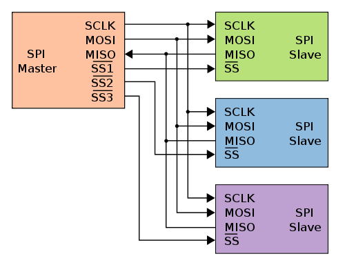
You can see the simplest of them in the figure above (thanks to Wikipedia for the drawings under the free GFDL license). In this case, all slaves are connected to the master in parallel, except for the slave select signal (~ CS). Each slave requires a separate slave select signal (in the figure they are designated as SSx). For the slave select signals, both the dedicated SPI controller outputs and the general purpose input / output ports (GPIO) of the microcontroller can be used.
Two conductors are used to transmit data, one to supply clock pulses and one slave select signal for each of the slaves.
Description of the signals used:
A special case of independent connection is the option with a single slave. In this case, you may want to tighten the ~ CS signal to the ground so that the device is always in the active state. But it is not recommended to do this, as the slave can use the CS signal for initialization or for other service purposes.
The main disadvantage of independent connection of slaves is that for each of the slaves a separate ~ CS signal is needed. The cascade connection scheme, in the foreign literature called “daisy-chain” (can be translated as “garland”), is deprived of such a disadvantage.

As can be seen from the figure above, here a common slave selection signal is used for all slaves. The output of each slave is connected to the input of the next. The output of the last slave is connected to the input of the master, thus forming a closed circuit. With such a connection, it can be assumed that the serially connected devices form one large shift register. Accordingly, the data can be written to all devices “in one sitting”, having previously assembled the necessary packet that combines the data for each of the devices in the order corresponding to the physical connection order. But there is one subtle point. Firstly, all microcircuits must support this type of connection; secondly, the Linux kernel does not support this type of connection, so if you still want to use it, then you will have to modify existing drivers, or write your own.
There are four modes of operation for SPI devices. As a rule, it is they who cause the most confusion among newbies. These four modes are a combination of two bits:
These two bits form the mode number. CPOL is the high bit and CPHA is the low bit. Sometimes the device documentation does not explicitly indicate the mode number, but it can always be easily identified by time diagrams. It is also important to understand that sampling and setting of data always occur on opposite fronts of the clock signal. For example, let our device operate in mode 0 (the most common option), in which case the slave device will read the data bit from the MOSI input on the rising edge of the clock signal, and the master device will also read data from the slave on the MISO input on the rising edge . For greater clarity, I will give oscillograms for all four modes of operation:
This figure shows the MOSI (blue line) and SCK (yellow line) signals. In all cases, the number 0x64 is transmitted. Light vertical lines show the moment of data sampling. Consider mode 2, for which, as we remember, CPOL = 1, and CPHA = 0. Thus, we see that the synchronizing signal initially has a high level, and the sampling is performed on the leading edge (in this case, falling). Since my oscilloscope has only two channels, the ~ CS and MISO signals are not shown. But in this case they are not so interesting, for example, the ~ CS signal is simply a “failure” throughout the data transmission.
Linux SPI drivers are divided into two parts. The first is the SPI controller drivers that work directly with the hardware of a particular controller. Such drivers determine how to configure the controller, what actions to take when switching to low power (suspend) mode and leaving it (resume), selecting the next transmission (spi_transfer) from the transmission queue in the message (spi_message, about queues just below) and sending it directly to the port, it is also determined how to activate / deactivate a specific device via CS (cs_activate / cs_deactivate functions). In this article I will not describe this type of drivers. As a rule, they are already implemented for those MCU / eMPUs for which there is a Linux port, and you need to use your hands only if you need some specific function, like Chip Select Decoding, to be able to activate the required slave device via an external logic. Sometimes it is useful, for example, in case of a lack of GPIO.
The second part is the protocol drivers used to work with various slave devices that are connected to the SPI bus. These drivers are called “protocol” drivers because they only send and receive various data from slave devices, while not working directly with any equipment. It is this type of drivers that is most interesting to us, since it allows us to add support for the slave of interest to the system, which we will consider.
Most protocol drivers are kernel modules. For example, if the device is an SPI audio codec, the driver will also use the functions provided by ALSA, and the programs (for example, madplay) will be able to work with it through the character device / dev / audio, without having the slightest idea about how it is hardware and which bus is connected.
The kernel also provides a general-purpose protocol driver, called spidev, with an interface in the form of a character device. It allows you to make half-duplex calls to a slave SPI device using standard read () and write () system calls, set the operation mode, and also perform full-duplex data exchange via ioctl () calls.
Thus, protocol drivers for SPI devices can be divided into two types:
All calls to SPI devices Linux is queuing. SPI protocol drivers operate explicitly or implicitly with messages represented by a struct spi_message structure, which is a multi-segment SPI transaction.
transfers - a linked list of transmitted segments in a transaction (transfers);
spi - a pointer to the spi device in which the given message is in the queue;
is_dma_maped - if this flag is true, then both dma and cpu virtual addresses are provided for each transmission buffer;
complete - callback, called to notify about the end of the transaction;
context - the argument for the complete () callback;
actual_length - the total number of bytes that were transmitted in all successful predacs;
status - 0 if successful, or a negative value with errno in case of an error;
The spi_message structure is used to perform an atomic sequence of data transmissions, each of which is represented by the spi_transfer structure. The sequence is “atomic” in the sense that the SPI bus cannot be used to transmit another spi_message message until the previous one has been completely sent. On some systems, many such sequences can be performed as a single programmed DMA transmission. On all systems, these messages are queued, and can be completed after transactions with other devices. All calls to a single slave device are always made in the FIFO order.
The struct spi_transfer structure describes a separate transmission in a linked list of a message and defines a pair of read / write buffers.
tx_buf - a pointer to the data buffer in the memory space of the kernel to be transferred, or NULL;
rx_buf - a pointer to the data buffer in the memory space of the kernel, in which the data should be counted, or NULL;
len - size of buffers rx and tx in bytes;
tx_dma - DMA address tx_buf, used if the spi_message.is_dma_mapped parameter is set;
rx_dma - DMA address rx_buf, used if the parameter spi_message.is_dma_mapped is set;
speed_hz - sets the speed for the transfer, different from the default for the device. If this value is 0, then the default speed specified in the max_speed_hz field of the spi_device structure is used .
bits_per_word - sets the number of bits per word other than the default. If this value is 0, then the default value specified in the bits_per_word field of the spi_device structure is used .
delay_usecs - waiting time in microseconds, after the last bit of the transmission was sent and before changing the state of the chipselect, or starting the transmission of the next transmission in the queue. Be extremely careful with this parameter, you need to look at which part of the controller driver the delay is implemented. For example, for chips of the at91 series, it is implemented in the interrupt handler, so its use is fraught with consequences.
When initializing the spi_transfer structure, there is a very important point, they must be allocated in the memory area accessible to DMA through kmalloc, kzalloc and their ilk. If the master driver uses dma, then when using statically declared arrays, the driver will crash when trying to transfer.
When transmitting data over SPI, the number of bits written is always equal to the number read. Protocol drivers must always provide pointers to the tx_buf and / or rx_buf buffers. In some cases, they may provide DMA addresses for transmitted data.
The possibility of redefining the data transfer rate and the number of bits per word for each transmission separately depends on the specific implementation of the driver and the controller's hardware capabilities. For example, for the SPI controller in at91 series chips, the possibility of overriding the speed_hz and bits_per_word fields is not provided, so they should always be set to 0, otherwise you will get an error when trying to transfer data.
If the pointer to tx_buf is set to NULL, then the SPI controller will push zeros while filling the rx_buf buffer. In the case where rx_buf is set to NULL, the read data will be ignored. The number of bytes ejected (and captured) is always equal to len. Attempting to push out only part of a word will result in an error. (For example, when trying to push three bytes and a word length of 16 bits or 20 bits, in the first case 2 bytes per word will be used, in the second - 4 bytes).
Data for transmission is always stored in a manner specific to the hardware platform. When sending / reading data, the byte order is automatically converted from SPI-specific (usually big-endian, except when SPI_LSB_FIRST is set) to a hardware-specific order for this CPU. For example, if the parameter bits_per_word is 16, then the buffers will occupy 2N bytes and contain N words with a length of 16 bits each, stored in byte order specific to this CPU.
In the event that the word size is not a power of two, then the representation of the word in memory includes additional bits. The words stored in the memory for the protocol driver are always right-justified, so the extra bits will always be high bits.
For clarity, again, give the waveform:
In this case, the tx-buffer contains the value 0xf98e, the set value of bits_per_word corresponds to 12 bits per word. The device works in SPI_MODE_0. In the figure, the blue line corresponds to the output of the MOSI controller, and the yellow line - SCK. Here you can clearly see that when sending, only 0x098e arrived, the upper four bits were discarded, as they are considered to be optional. If it is quite simple, then one 12-bit word occupies two bytes in memory, and the difference between the size of the word in memory and its actual size is 2 * 8 - 12 = 4 bits, which are discarded during transmission.
All SPI transmissions begin with the activation of the corresponding chipselect. Usually, the slave remains active until the last transmission in the message. Drivers can change the cs state by means of the cs_change flag in the spi_transfer structure.
The code that sends spi_message (and its spi_transfer'y) to the lower levels is responsible for managing the data memory of the structures. All fields of structures not explicitly defined, must be initialized to zero. After sending the message (and the individual transmissions in it), you need to ignore subsequent messages until the callback completes the message.
SPI does not support any automatic device discovery mechanism. In addition, in most cases, SPI devices do not provide for hot plugging / unplugging, therefore, as a rule, they are simply unsoldered directly on the board. In this connection, these devices are considered board-specific. The parameters for such devices are specified in the board file: arch /.../ mach - * / board - *. C.
For example, this is how setting parameters for the audio codec tlv320aic23b for the SK-AT91SAM9260 debug board will look like:
where modalias is the name of the kernel driver responsible for servicing the device (in our case “tlv320aic23b”);
chip_select - the number of the corresponding chip select;
max_speed_hz - maximum frequency in Hz;
mode - SPI mode, defined by the constants SPI_MODE_0 ... SPI_MODE_3, also through the bit or operation, the flags SPI_CS_HIGH can be added (sets the active level to high for the chipselect), SPI_NO_CS (data transmission without CS activation in principle). A complete list of possible flags can be found in the description of the spi_device structure;
bus_num is the bus number (as a rule, it corresponds to the SPI number of the controller in the datasheet on the MCU / eMPU).
Also, the spi_board_info structure contains the following fields that were not initialized in the example above:
const void * platform_data - this field is intended to store a pointer to driver-specific data;
void * controller_data - for some controllers, information on device configuration is required, for example, DMA;
int irq - depends on device connection.
All fields in the spi_board_info structure set the corresponding fields in the spi_device structure.
If it is necessary to set parameters for other SPI devices, more similar elements are added to the array.
These structures store information that cannot always be determined by drivers. Information that can be determined by the driver's probe () function (for example, the number of bits per word) is not included in this structure.
It is worth noting that there is still the possibility of hot plugging slave SPI devices. In this case, the spi_busnum_to_master () function is used to obtain a pointer to the spi_master structure using the SPI bus number and further search for devices on the bus. But this topic is beyond the scope of this article.
Read the second part
0. Instead of introducing
What is this article?
This article is a compilation of information from various sources, free translation of some parts of the documentation, as well as my own comments, additions and descriptions of the problems encountered.
Who is this article for?
First of all, for beginners, which I am. On the embedded Linux forums, you can often meet the question: “How do you work with SPI on this board?”. It is on him that I will try to give an answer. As an example, I will give the code written to work with my test SPI device.
Article structure
Due to the fact that there was a lot of information, the article is divided into several subsections:
- What is SPI?
- An overview of the SPI subsystem in Linux
- Developing userspace protocol SPI driver using spidev
- Development of a protocol SPI kernel-level driver
- Documentation
The first two points will be included in the first part of the article, remaining in the second.
')
The first subsection describes the operation of the SPI bus, this part of the article is not specifically tied to Linux, so it can be read by those who are not interested in Linux, but need only get information about this interface.
The second subsection describes the structures and mechanisms underlying working with SPI in Linux, it should be read to understand what will be discussed in the third and fourth parts.
If you are not interested in my translations and additions, feel free to skip straight to the fifth part, where you can find information on where to get all the necessary information on this issue.
If you see links in the name of any structure or function, you can open it in a new tab, so you can get directly to the description of this structure / function in the official documentation for the Linux kernel.
Errors
I'm not a magician, I'm just learning. If you find any errors or inaccuracies, please let me know.
1. What is SPI?
The abbreviation SPI means "Serial Peripheral Interface" or, in the Russian version, "serial peripheral interface". The name speaks for itself, this interface is used to work with various peripheral devices. For example, it can be various D / A converters, potentiometers, sensors, input / output port extenders (GPIO), different memory, and even more complex peripherals, such as audio codecs and Ethernet controllers.
From a technical point of view, SPI is a synchronous four-wire bus. It is a combination of two synchronous shift registers, which is the central element of any SPI device. For the connection, the master / slave configuration is used. Only the master can generate synchronization pulses. In the scheme, there is always only one master (unlike the same I2C bus, where a variant with more than one master is possible), the number of slaves may be different. In general, the master output is connected to the slave input, and vice versa, the slave output is connected to the master input. When applying synchronization pulses to the SCK output, data is pushed by the master from the MOSI output, and captured by the slave on the MISO input. Thus, if we submit the number of synchronization pulses corresponding to the digit capacity of the shift register, the data in the registers will exchange places. It follows that SPI always works in full duplex mode. But do we need the data received from the device when writing any parameter, that is another question. It often happens that the data received from the device when writing data to it is garbage, in which case they are simply ignored, but we will receive it regardless of our desire.
An SPI controller is typically implemented by a peripheral unit in an MCU or eMPU. In most chips, it can operate in both master mode and slave mode. But at the moment Linux only supports Master mode.
There are several ways to enable SPI devices.
You can see the simplest of them in the figure above (thanks to Wikipedia for the drawings under the free GFDL license). In this case, all slaves are connected to the master in parallel, except for the slave select signal (~ CS). Each slave requires a separate slave select signal (in the figure they are designated as SSx). For the slave select signals, both the dedicated SPI controller outputs and the general purpose input / output ports (GPIO) of the microcontroller can be used.
Two conductors are used to transmit data, one to supply clock pulses and one slave select signal for each of the slaves.
Description of the signals used:
- MOSI - Master Output, Slave Input (master output, slave input). This signal is intended for serial data transmission from master to slave. Also referred to as SDO, DO, etc.
- MISO - Master Input, Slave Output (master input, slave output). This signal is intended for serial data transmission from the slave to the master. May be called SDI, DI, etc.
- SCK - Serial Clock (synchronization signal). Used to synchronize when transferring data. It may also be called SCLK, CLK, etc.
- ~ CS - Chip Select (chip select). This signal activates the slave. It is usually inverse, that is, a low level is considered active. Sometimes it is called ~ SS (Slave Select, Russian. "Slave Select").
A special case of independent connection is the option with a single slave. In this case, you may want to tighten the ~ CS signal to the ground so that the device is always in the active state. But it is not recommended to do this, as the slave can use the CS signal for initialization or for other service purposes.
The main disadvantage of independent connection of slaves is that for each of the slaves a separate ~ CS signal is needed. The cascade connection scheme, in the foreign literature called “daisy-chain” (can be translated as “garland”), is deprived of such a disadvantage.
As can be seen from the figure above, here a common slave selection signal is used for all slaves. The output of each slave is connected to the input of the next. The output of the last slave is connected to the input of the master, thus forming a closed circuit. With such a connection, it can be assumed that the serially connected devices form one large shift register. Accordingly, the data can be written to all devices “in one sitting”, having previously assembled the necessary packet that combines the data for each of the devices in the order corresponding to the physical connection order. But there is one subtle point. Firstly, all microcircuits must support this type of connection; secondly, the Linux kernel does not support this type of connection, so if you still want to use it, then you will have to modify existing drivers, or write your own.
There are four modes of operation for SPI devices. As a rule, it is they who cause the most confusion among newbies. These four modes are a combination of two bits:
- CPOL (Clock Polarity) - determines the initial level (polarity) of the synchronization signal.
CPOL = 0 indicates that the synchronization signal starts from a low level, so that the leading edge is increasing, and the rear edge is falling.
CPOL = 1, the synchronization signal starts from a high level, so the leading edge is falling, and the rear is increasing. - CPHA (Clock Phase) - phase synchronization, determines which of the edges of the clock signal to sample data.
CPHA = 0 indicates that it is necessary to sample on the leading edge, and
CPHA = 1 indicates that data should be sampled at the falling edge.
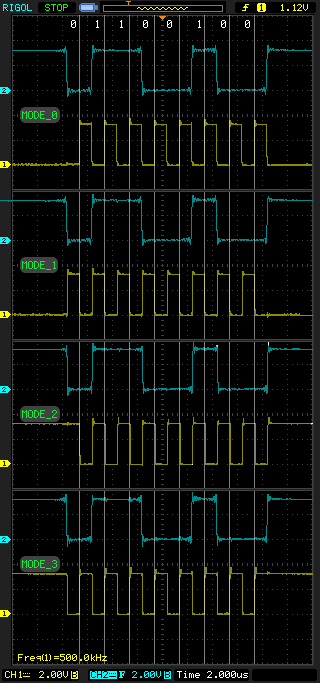
These two bits form the mode number. CPOL is the high bit and CPHA is the low bit. Sometimes the device documentation does not explicitly indicate the mode number, but it can always be easily identified by time diagrams. It is also important to understand that sampling and setting of data always occur on opposite fronts of the clock signal. For example, let our device operate in mode 0 (the most common option), in which case the slave device will read the data bit from the MOSI input on the rising edge of the clock signal, and the master device will also read data from the slave on the MISO input on the rising edge . For greater clarity, I will give oscillograms for all four modes of operation:
This figure shows the MOSI (blue line) and SCK (yellow line) signals. In all cases, the number 0x64 is transmitted. Light vertical lines show the moment of data sampling. Consider mode 2, for which, as we remember, CPOL = 1, and CPHA = 0. Thus, we see that the synchronizing signal initially has a high level, and the sampling is performed on the leading edge (in this case, falling). Since my oscilloscope has only two channels, the ~ CS and MISO signals are not shown. But in this case they are not so interesting, for example, the ~ CS signal is simply a “failure” throughout the data transmission.
2. Overview of the SPI subsystem in Linux
Linux SPI drivers are divided into two parts. The first is the SPI controller drivers that work directly with the hardware of a particular controller. Such drivers determine how to configure the controller, what actions to take when switching to low power (suspend) mode and leaving it (resume), selecting the next transmission (spi_transfer) from the transmission queue in the message (spi_message, about queues just below) and sending it directly to the port, it is also determined how to activate / deactivate a specific device via CS (cs_activate / cs_deactivate functions). In this article I will not describe this type of drivers. As a rule, they are already implemented for those MCU / eMPUs for which there is a Linux port, and you need to use your hands only if you need some specific function, like Chip Select Decoding, to be able to activate the required slave device via an external logic. Sometimes it is useful, for example, in case of a lack of GPIO.
The second part is the protocol drivers used to work with various slave devices that are connected to the SPI bus. These drivers are called “protocol” drivers because they only send and receive various data from slave devices, while not working directly with any equipment. It is this type of drivers that is most interesting to us, since it allows us to add support for the slave of interest to the system, which we will consider.
Most protocol drivers are kernel modules. For example, if the device is an SPI audio codec, the driver will also use the functions provided by ALSA, and the programs (for example, madplay) will be able to work with it through the character device / dev / audio, without having the slightest idea about how it is hardware and which bus is connected.
The kernel also provides a general-purpose protocol driver, called spidev, with an interface in the form of a character device. It allows you to make half-duplex calls to a slave SPI device using standard read () and write () system calls, set the operation mode, and also perform full-duplex data exchange via ioctl () calls.
Thus, protocol drivers for SPI devices can be divided into two types:
- userspace drivers that work in user space and are regular programs in any language that work with an SPI device by reading / writing the corresponding character device spidev.
- kernel-spaced drivers that provide an interface for userspace through device files in the / dev directory, or using attributes in the device directory in sysfs.
All calls to SPI devices Linux is queuing. SPI protocol drivers operate explicitly or implicitly with messages represented by a struct spi_message structure, which is a multi-segment SPI transaction.
struct spi_message { struct list_head transfers; struct spi_device *spi; unsigned is_dma_mapped:1; void (*complete)(void *context); void *context; unsigned actual_length; int status; struct list_head queue; void *state; }; transfers - a linked list of transmitted segments in a transaction (transfers);
spi - a pointer to the spi device in which the given message is in the queue;
is_dma_maped - if this flag is true, then both dma and cpu virtual addresses are provided for each transmission buffer;
complete - callback, called to notify about the end of the transaction;
context - the argument for the complete () callback;
actual_length - the total number of bytes that were transmitted in all successful predacs;
status - 0 if successful, or a negative value with errno in case of an error;
The spi_message structure is used to perform an atomic sequence of data transmissions, each of which is represented by the spi_transfer structure. The sequence is “atomic” in the sense that the SPI bus cannot be used to transmit another spi_message message until the previous one has been completely sent. On some systems, many such sequences can be performed as a single programmed DMA transmission. On all systems, these messages are queued, and can be completed after transactions with other devices. All calls to a single slave device are always made in the FIFO order.
The struct spi_transfer structure describes a separate transmission in a linked list of a message and defines a pair of read / write buffers.
struct spi_transfer { const void *tx_buf; void *rx_buf; unsigned len; dma_addr_t tx_dma; dma_addr_t rx_dma; unsigned cs_change:1; u8 bits_per_word; u16 delay_usecs; u32 speed_hz; struct list_head transfer_list; }; tx_buf - a pointer to the data buffer in the memory space of the kernel to be transferred, or NULL;
rx_buf - a pointer to the data buffer in the memory space of the kernel, in which the data should be counted, or NULL;
len - size of buffers rx and tx in bytes;
tx_dma - DMA address tx_buf, used if the spi_message.is_dma_mapped parameter is set;
rx_dma - DMA address rx_buf, used if the parameter spi_message.is_dma_mapped is set;
speed_hz - sets the speed for the transfer, different from the default for the device. If this value is 0, then the default speed specified in the max_speed_hz field of the spi_device structure is used .
bits_per_word - sets the number of bits per word other than the default. If this value is 0, then the default value specified in the bits_per_word field of the spi_device structure is used .
delay_usecs - waiting time in microseconds, after the last bit of the transmission was sent and before changing the state of the chipselect, or starting the transmission of the next transmission in the queue. Be extremely careful with this parameter, you need to look at which part of the controller driver the delay is implemented. For example, for chips of the at91 series, it is implemented in the interrupt handler, so its use is fraught with consequences.
When initializing the spi_transfer structure, there is a very important point, they must be allocated in the memory area accessible to DMA through kmalloc, kzalloc and their ilk. If the master driver uses dma, then when using statically declared arrays, the driver will crash when trying to transfer.
When transmitting data over SPI, the number of bits written is always equal to the number read. Protocol drivers must always provide pointers to the tx_buf and / or rx_buf buffers. In some cases, they may provide DMA addresses for transmitted data.
The possibility of redefining the data transfer rate and the number of bits per word for each transmission separately depends on the specific implementation of the driver and the controller's hardware capabilities. For example, for the SPI controller in at91 series chips, the possibility of overriding the speed_hz and bits_per_word fields is not provided, so they should always be set to 0, otherwise you will get an error when trying to transfer data.
If the pointer to tx_buf is set to NULL, then the SPI controller will push zeros while filling the rx_buf buffer. In the case where rx_buf is set to NULL, the read data will be ignored. The number of bytes ejected (and captured) is always equal to len. Attempting to push out only part of a word will result in an error. (For example, when trying to push three bytes and a word length of 16 bits or 20 bits, in the first case 2 bytes per word will be used, in the second - 4 bytes).
Data for transmission is always stored in a manner specific to the hardware platform. When sending / reading data, the byte order is automatically converted from SPI-specific (usually big-endian, except when SPI_LSB_FIRST is set) to a hardware-specific order for this CPU. For example, if the parameter bits_per_word is 16, then the buffers will occupy 2N bytes and contain N words with a length of 16 bits each, stored in byte order specific to this CPU.
In the event that the word size is not a power of two, then the representation of the word in memory includes additional bits. The words stored in the memory for the protocol driver are always right-justified, so the extra bits will always be high bits.
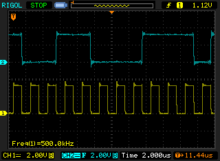
For clarity, again, give the waveform:
In this case, the tx-buffer contains the value 0xf98e, the set value of bits_per_word corresponds to 12 bits per word. The device works in SPI_MODE_0. In the figure, the blue line corresponds to the output of the MOSI controller, and the yellow line - SCK. Here you can clearly see that when sending, only 0x098e arrived, the upper four bits were discarded, as they are considered to be optional. If it is quite simple, then one 12-bit word occupies two bytes in memory, and the difference between the size of the word in memory and its actual size is 2 * 8 - 12 = 4 bits, which are discarded during transmission.
All SPI transmissions begin with the activation of the corresponding chipselect. Usually, the slave remains active until the last transmission in the message. Drivers can change the cs state by means of the cs_change flag in the spi_transfer structure.
- If the transfer is not the last in the message, then the cs_change flag is used to chipselect for a short time to become inactive in the middle of the message. Such cs switching may be necessary to complete the slave command. This allows using one spi_message to execute immediately a group of transfers for one slave.
- When the transmission is the last in the message, the slave may remain selected until the transmission of the next message begins. Starting a message transfer to another device deactivates the current cs. For some devices, transactions must consist of a spi_message message queue, where the content of the subsequent message depends on the result of the previous ones. In this case, the entire transaction is completed by putting the cs in an inactive state.
The code that sends spi_message (and its spi_transfer'y) to the lower levels is responsible for managing the data memory of the structures. All fields of structures not explicitly defined, must be initialized to zero. After sending the message (and the individual transmissions in it), you need to ignore subsequent messages until the callback completes the message.
SPI does not support any automatic device discovery mechanism. In addition, in most cases, SPI devices do not provide for hot plugging / unplugging, therefore, as a rule, they are simply unsoldered directly on the board. In this connection, these devices are considered board-specific. The parameters for such devices are specified in the board file: arch /.../ mach - * / board - *. C.
For example, this is how setting parameters for the audio codec tlv320aic23b for the SK-AT91SAM9260 debug board will look like:
static struct spi_board_info ek_spi_devices[] = { { /* tlv320aic23b CODEC */ .modalias = "tlv320aic23b", .chip_select = 0, .max_speed_hz = 10 * 1000 * 1000, .bus_num = 1, .mode = SPI_MODE_1, .platform_data = &tlv320aic23b_data, }, … } where modalias is the name of the kernel driver responsible for servicing the device (in our case “tlv320aic23b”);
chip_select - the number of the corresponding chip select;
max_speed_hz - maximum frequency in Hz;
mode - SPI mode, defined by the constants SPI_MODE_0 ... SPI_MODE_3, also through the bit or operation, the flags SPI_CS_HIGH can be added (sets the active level to high for the chipselect), SPI_NO_CS (data transmission without CS activation in principle). A complete list of possible flags can be found in the description of the spi_device structure;
bus_num is the bus number (as a rule, it corresponds to the SPI number of the controller in the datasheet on the MCU / eMPU).
Also, the spi_board_info structure contains the following fields that were not initialized in the example above:
const void * platform_data - this field is intended to store a pointer to driver-specific data;
void * controller_data - for some controllers, information on device configuration is required, for example, DMA;
int irq - depends on device connection.
All fields in the spi_board_info structure set the corresponding fields in the spi_device structure.
If it is necessary to set parameters for other SPI devices, more similar elements are added to the array.
These structures store information that cannot always be determined by drivers. Information that can be determined by the driver's probe () function (for example, the number of bits per word) is not included in this structure.
It is worth noting that there is still the possibility of hot plugging slave SPI devices. In this case, the spi_busnum_to_master () function is used to obtain a pointer to the spi_master structure using the SPI bus number and further search for devices on the bus. But this topic is beyond the scope of this article.
Read the second part
Source: https://habr.com/ru/post/123145/
All Articles