Security system, smart home project (part 1)
 Many wanted to protect their apartment from being hacked, because the majority of the systems on the market are unlikely to be affordable for many. However, having experience and knowledge in electronics and microprocessor technology, this can be done easily by yourself. Below we will explain how you can make an “intelligent” security loop out of the available and inexpensive tools with the ability to display data on a computer, tablet or phone with an operating system. 2nd part .
 Task setting and selection of elements for the security system
The security system can be divided into two blocks: the control panel (control panel) and security loop (OSH). Moreover, the control panel provides power to security loops, receiving messages from sensors located on the loop, processing the received information, generating alarm messages and transmitting them further. The main task of security loops is the connection of sensors or detectors and connection to the control panel, and from 1 to N sensors can be located on one loop and is primarily related to which sensors on the cable are digital or analog, if digital, which interface is used for information exchange with the control panel. In our case, there was a goal of developing an inexpensive security device, which means that an analog cable was chosen for prototyping (before the explanation, it is better to view the picture below).
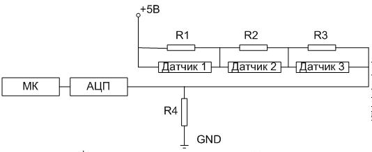
As can be seen from the picture, a resistor with a certain resistance is connected in parallel to each analog sensor. The sensors can be used: infrared motion detector, glass break sensor, door opening sensor. As can be seen from the above, on one loop, with the correct processing of incoming information, you can protect the entire apartment from hacking. To do this, and to test the performance of the loop in the prototype, simple switches were used, which simulate these sensors.

An example of the layout of the loop using switches
The readings were also taken from the terminal resistor, and thanks to the construction of a loop using this principle, we were able to know which switch worked exactly. After all, when closing certain switches, on which different resistances of resistors are suspended, on the terminal resistor there will always be a different value of the voltage drop ranging from supply voltage to zero.
The voltage taken from the terminal resistor is an analog value, then we need an analog-to-digital converter (ADC) to process the received data for further processing of information in the processor. Based on the above, a C8051F310 processor with an integrated 10-bit ADC was selected. A block diagram of the resulting system is presented below.
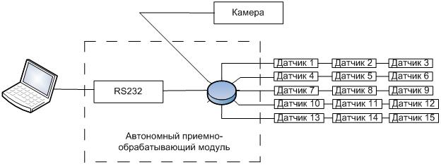
And since there was a need to visualize the received information on a computer, RS232 was chosen for the communication interface, for its popularity and “chew” (in almost any forum of radio amateurs and a programmer you can find recommendations for using it). Based on this, the MAX202 chip was chosen to support this interface.
')
Development environments
When creating a prototype, it became necessary to write programs for both the processor (lower level) and the computer (upper level).
The lower level was developed in the Keil 4 environment, designed for the 8051 family of controllers and incorporating the C compiler. UART interface unit to the computer, which completely repeats the functions of the control panel.
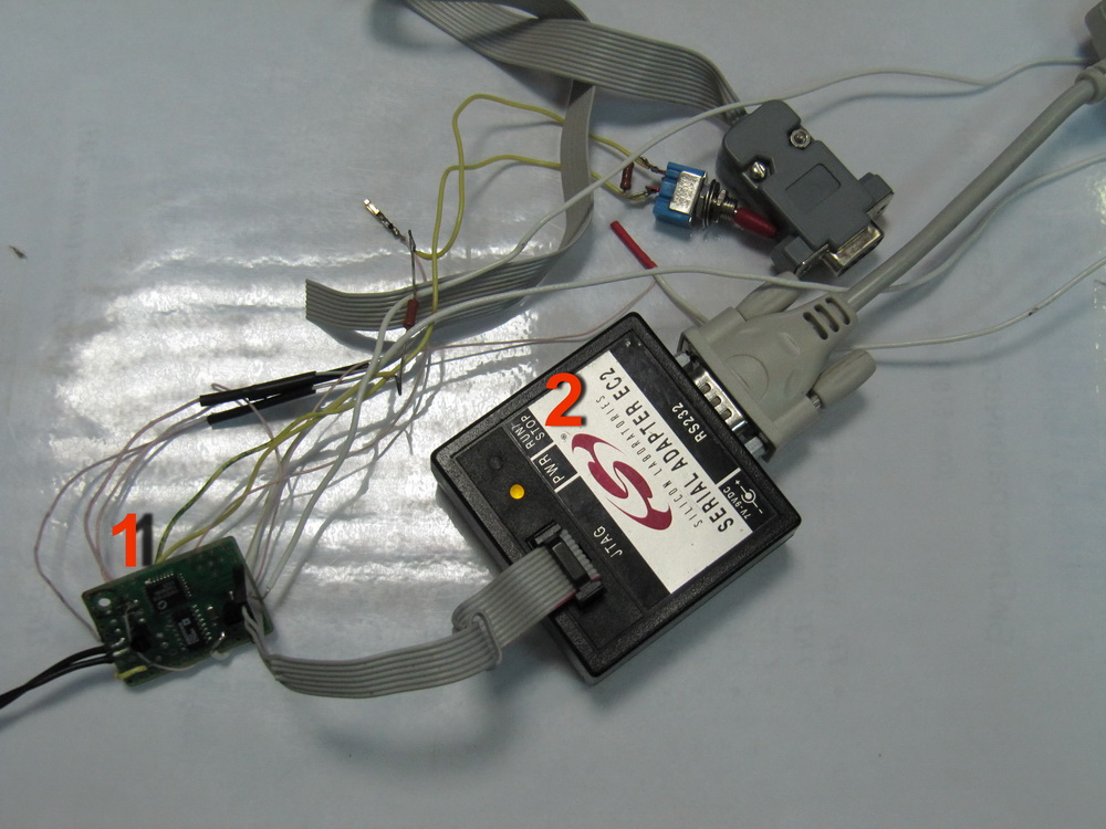
Controller programming
The top level was developed in the Borland Builder 6 C ++ environment. The written program performs the following functions: decryption of the received code from the microprocessor, visualization of information on the screen.
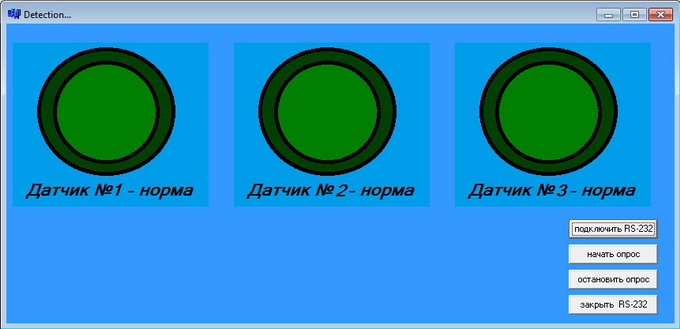
Program window
Program codes can be found on the project page .
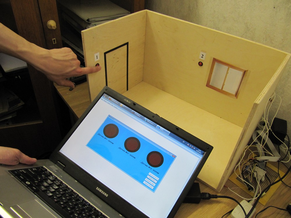
Mockup sample
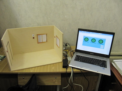
After debugging, the layout of the apartment and the connected system was made. The results are shown below.

All switches are turned off, information on the computer is displayed as the norm for all sensors.

Switch number 3 is on, information on the computer is displayed as a threat to the third sensor

Switches No. 2, No. 3 are on, information on the computer is displayed as a threat to the second and third sensors.
Switches No. 1-3 are turned on, information on the computer is displayed as a threat to all sensors.
Results and development plans
During the prototyping, it was worked out: reception and decoding of signals received from analog sensors and transmission and display of information to a computer. In the future, information from the controller will be available remotely (data transmission via the Internet), as well as control (switching the system on and off) and receiving reports via our own twitter account.
2nd part .
Source: https://habr.com/ru/post/122015/
All Articles