256-byte assembler driven gradient helix (k29)
This article is devoted to the creation of a graphics application weighing several hundred bytes on an assembler. After creating a full working version of 420 bytes, I had to sweat to stuff all this stuff into 256 bytes. You can see the result on the video. The article describes the process of creation and general principles of operation.
Warning: If you are suffering from epilepsy, DO NOT LOOK.
In Win7 and Vista will not work. Need Windows XP / 2000/98.
')
Download executable file: k29.com in DropBox (256 bytes)
Download source code: k29.asm in DropBox (Compile with FASM)
Control keys:
1. R, G, B - enable and disable color components
2. <-, SPACE, -> - change the direction and speed of rotation
3. UP, DOWN - change the scale of the spiral
4. 0,1,2,3,4,5,6,7,8,9 - change the number of branches at the spiral
5. ESC - exit
For quite a while this article has been lying around in my drafts. More in the drafts on Blogger-e. And today I decided that if I didn’t add it now, it would never happen. I finished, at the end I cut off a bit and finished) Hooray !!!
I have always been interested in working with demoparty, especially categories in hundreds of bytes. It's one thing to write a 64 kilo prog program using DirectX / OpenGL, and quite another in 512/256/128 bytes, using video memory directly, etc. It requires the knowledge and understanding of the assembler is already on an intuitive level. It is necessary to be able to optimize the code in terms of volume, and therefore to understand and take into account all the subtleties of the machine programming language. We will try to do something similar. I have never written in assembler before, but it worked out to understand the existing code. We assume that this article is aimed at newcomers to an assembler like me. Because I do not pretend to be the perfect solution to the problem.
Now you need to come up with a task and implement it. Immediately, a small program written in school years in the Pascal language came to mind. The program was simple to disgrace (2 screens of code - 50 lines), but at the same time it delivered. The program drew in a graphic mode (320x200x256) a rotating spiral in full screen. All 256 colors were used for a smooth color change. It was surprising that the spiral moves without visible redrawing. This could be explained by the use of several video pages, if not for the speed of rotation. Obviously, to draw a spiral, calculations with real numbers are necessary, which also introduces a significant delay. The spiral rotated at a speed of 3-5 revolutions per second (see. Fig. 2.1).

[Fig. 2.1. A snapshot of a three-handed helix]
And the whole point was that the spiral was drawn only once - when the program was started. After drawing the spiral, the program cyclically shifted the colors in the palette, which was immediately displayed on the screen. In addition to the main function, the program supported a change in the color of the spiral and a change in the direction of rotation. Only eight colors:
Since the RGB color model is used for display on the screen, these eight colors can be obtained by combining the corresponding color components (3 data bits can encode 8 different values). The program used the 'R', 'G' and 'B' keys to enable / disable the corresponding color components.
The program was written in Pascal in the Turbo Pascal 7.0 development environment. Some functions of the program were implemented in the form of assembler inserts. For example, the function of setting the RGB value to a specific element from the palette. The code of school times (formatting is changed so as not to traumatize the psyche draw):
First, let's look at how the program works and what functions we need to write. The formal description of the algorithm:
1) Initial filling of the palette with the following values: (0,0,0) ... (63,63,63) ... (0,0,0). In other words, throughout the 256 elements of the palette, the color smoothly changes from black to white and returns to black again. In this graphic mode, up to 256 colors are supported, each of the colors consists of three color components. Each of the color components is given in six bits (a number from 0 to 63). White color corresponds to the vector of color components (63,63,63), and black, respectively - (0,0,0).
2) Drawing a spiral involves traversing all the pixels on the screen and filling them with data. The formula of the spiral is quite simple - it depends only on the vector (a pair of values: distance and angle) indicating a specific pixel from the center of the screen. In other words, color depends only on the length of the vector and the angle of the vector with selected coefficients. Looking through various coefficients, one can get both a different number of “branches” of a spiral and a different degree of its twisting.
3) Cyclic shift of the palette by one position. This gives the illusion of rotation of the spiral. That is, by changing 256 color elements, we get a shift of the helix by 1 / (256 * k) full rotation. Where k is the number of "branches" of the spiral. Thus, we avoided redrawing all pixels of the screen to rotate the spiral. In fact, we will not shift to a “one” position, the magnitude and direction of the shift are stored in a special integer variable. This will allow us to dynamically change the direction and speed of rotation of the spiral.
4) Check keystrokes. Pressing the R, G and B keys leads to the activation or deactivation of the color component assigned to each of the keys. Pressing the "right" / "left" keys increases / decreases the value of a variable that is explicitly used when the palette is shifted. Go to point 3.
Well, now we define what functions we need to write in assembly language. Obviously, these will be: the initial filling function of the palette, the spiral drawing function, the cyclic shift function of the palette and the main function of the program, which, in addition to calling the above functions, will ensure that the control keys are pressed on the keyboard. The flowchart of the algorithm:
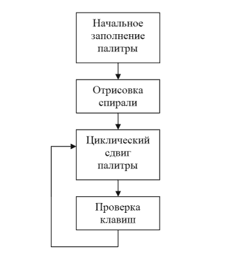
[Fig. 4.1. Algorithm block diagram]
After reading about the available assembler language compilers in Wikipedia and the book “The Art of Disassembling” by Chris Kaspersky and Eva Rocco, I made my choice in favor of the FASM compiler. I will write the code in Notepad ++, and from it I will export to an article with syntax highlighting.
Well, let's get started.
We are going to fill the palette with the following values: (0,0,0), ... (63,63,63), ... (0,0,0). It is easy to calculate that there are a total of 127, to uniformly fill all 256 elements, we will fill in 2 identical elements: (0,0,0), (0,0,0), ... (63,63,63), (63 , 63.63), ... (0,0,0), (0,0,0). We write the algorithm in a formal high level language:
Now the assembler code with comments:
A. We save in the stack and restore from the stack the registers that are used in the function.
B. The CX register runs in a loop from 0 to 127, inclusive.
C. Form the parameters and call the setPalette function. In AL, we load a color index, in AH, we load a brightness value equal to half the index.
D. Change the index to (255-i) using the operation of inverting all bits and calling the function setPalette.
Consider the description function of the gradient spiral.
The function depending only on the radius gives gradient circles:

[Fig. 4.1. Gradient Circles]
The function depending only on the angle gives the gradient rays from the center:

[Fig. 4.2. Gradient Rays]
The function, which is linearly dependent on the radius and angle, will give us the desired gradient spiral:

[Fig. 4.3. Gradient Spiral]
It is only necessary to choose the necessary coefficients for a 360-degree regular drawing of the spiral. The coefficient k1 affects only the degree of spiral twisting. For the correct filling of 360 degrees, choose the coefficient k3 as follows:
[Fig. 4.4. Correct 360 Gradient Spiral]
The k2 coefficient will take integer values: 1, 2, 3, 4 ... Changing this coefficient, we get the corresponding number of branches at the helix. Examples of gradient spirals with k2 equal to one, two and five are presented in Fig. 4.5, 4.6 and 4.7:

[Fig. 4.5. Spiral with one branch]

[Fig. 4.6. Spiral with two branches]

[Fig. 4.7. Spiral with five branches]
Spiral drawing code in pseudo-language:
(Without taking into account possible errors, including division by zero)
Now we implement the algorithm in assembler.
A. We save in the stack and restore from the stack the registers that are used in the function.
B. The register AX runs in a loop from 0 to 199 inclusive.
C. The BX register runs in a loop from 0 to 319 inclusive.
D. Store AX and BX on the stack. Align the coordinates of the center of the spiral on the screen, for a resolution of 320x200 we shift the center by the middle - (160, 100). Recover AX and BX from the stack.
E. We build AX in a square, we swap the value of registers AX and BX, once again we build AX in a square. We have in the registers AX and BX square coordinates. Add the register values and load the result into the DX.
Calculating the root is quite possible to sacrifice in favor of reducing the size of the application code. It would be good to save the AX and BX registers on the stack and restore them back when calculating the length of a vector:
Now the code that calculates the angle angle for given sin and cos:
I think the code has already got everyone)) This is where it lies entirely: http://codepad.org/mEDX1Z2X
You can also reduce the amount of code by removing the extra control keys. I think if you throw out all the controls you can easily keep within 128 bytes. But without control is not so interesting.
Warning: If you are suffering from epilepsy, DO NOT LOOK.
In Win7 and Vista will not work. Need Windows XP / 2000/98.
')
Download executable file: k29.com in DropBox (256 bytes)
Download source code: k29.asm in DropBox (Compile with FASM)
Control keys:
1. R, G, B - enable and disable color components
2. <-, SPACE, -> - change the direction and speed of rotation
3. UP, DOWN - change the scale of the spiral
4. 0,1,2,3,4,5,6,7,8,9 - change the number of branches at the spiral
5. ESC - exit
Epilogue
For quite a while this article has been lying around in my drafts. More in the drafts on Blogger-e. And today I decided that if I didn’t add it now, it would never happen. I finished, at the end I cut off a bit and finished) Hooray !!!
1. The plot
I have always been interested in working with demoparty, especially categories in hundreds of bytes. It's one thing to write a 64 kilo prog program using DirectX / OpenGL, and quite another in 512/256/128 bytes, using video memory directly, etc. It requires the knowledge and understanding of the assembler is already on an intuitive level. It is necessary to be able to optimize the code in terms of volume, and therefore to understand and take into account all the subtleties of the machine programming language. We will try to do something similar. I have never written in assembler before, but it worked out to understand the existing code. We assume that this article is aimed at newcomers to an assembler like me. Because I do not pretend to be the perfect solution to the problem.
2. Choosing a goal
Now you need to come up with a task and implement it. Immediately, a small program written in school years in the Pascal language came to mind. The program was simple to disgrace (2 screens of code - 50 lines), but at the same time it delivered. The program drew in a graphic mode (320x200x256) a rotating spiral in full screen. All 256 colors were used for a smooth color change. It was surprising that the spiral moves without visible redrawing. This could be explained by the use of several video pages, if not for the speed of rotation. Obviously, to draw a spiral, calculations with real numbers are necessary, which also introduces a significant delay. The spiral rotated at a speed of 3-5 revolutions per second (see. Fig. 2.1).
[Fig. 2.1. A snapshot of a three-handed helix]
And the whole point was that the spiral was drawn only once - when the program was started. After drawing the spiral, the program cyclically shifted the colors in the palette, which was immediately displayed on the screen. In addition to the main function, the program supported a change in the color of the spiral and a change in the direction of rotation. Only eight colors:
| 0 | # 000000 | Black (helix not visible) |
| one | # 0000FF | Blue |
| 2 | # 00FF00 | Bright green |
| 3 | # 00FFFF | Turquoise |
| four | # FF0000 | Red |
| five | # FF00FF | Purple |
| 6 | # FFFF00 | Yellow |
| 7 | #FFFFFF | White |
Since the RGB color model is used for display on the screen, these eight colors can be obtained by combining the corresponding color components (3 data bits can encode 8 different values). The program used the 'R', 'G' and 'B' keys to enable / disable the corresponding color components.
The program was written in Pascal in the Turbo Pascal 7.0 development environment. Some functions of the program were implemented in the form of assembler inserts. For example, the function of setting the RGB value to a specific element from the palette. The code of school times (formatting is changed so as not to traumatize the psyche draw):
program P_16_B_4; uses crt,graph,MUSE_OTH,MT_MAIN; const koef1=3;{ } koef2=3;{ } var gd,gm,gmx,gmy,i,flag,x0,y0,x,y:integer; r,alpha:extended; k,int:longint; key:char;rr,gg,bb:byte; ints:string; mas:array[0..255,1..3] of byte; BEGIN gd:=installuserdriver('SVGA256m.BGI',NIL);gm:=2; initgraph(gd,gm,''); gmx:=getmaxx; gmy:=getmaxy; flag:=1;k:=1; for i:=0 to 255 do begin setRGBpalette(i,k,k,k); mas[i,1]:=k;mas[i,2]:=k;mas[i,3]:=k; k:=k+flag; if k=63 then flag:=-1 else if k=0 then flag:=1; end; setcolor(63); settextstyle(1,horizdir,2); settextjustify(centertext,centertext); outtextxy(gmx div 2,gmy div 2-textheight('!<06@')*2 div 2, '!<06@ freeware'); outtextxy(gmx div 2,gmy div 2+textheight('!<06@') div 2, '! ! ! Press "R", "G", "B", " " or "Esc" ! ! !'); x0:=gmx div 2; y0:=gmy div 2; r:=400; repeat alpha:=0; repeat x:=round(x0+r*cos(alpha/180*Pi)); y:=round(y0-r*sin(alpha/180*Pi)); putpixel(x,y,round(r*koef2+alpha*256/360*koef1/2) mod 128); alpha:=alpha+20/(r+1); until alpha>=360; if keypressed then halt; r:=r-1; until r<=0; k:=1;flag:=-1;rr:=1;gg:=1;bb:=1;int:=0; repeat str(int SHR 2,ints); while byte(ints[0])<4 do insert('0',ints,1); if int and 3=0 then SAVE_MONITOR((gmx+1) div 2-75,(gmy+1) div 2-75,(gmx+1) div 2+74, (gmy+1) div 2+74,'c:\AVATAR\'+ints+'.bmp'); if keypressed then begin key:=readkey; if key=' ' then flag:=-flag else if upcase(key)='R' then rr:=not(rr) and 1 else if upcase(key)='G' then gg:=not(gg) and 1 else if upcase(key)='B' then bb:=not(bb) and 1 else if key=#27 then break; end; for i:=0 to 127 do setRGBpalette(i,mas[(i+k+512) mod 256,1]*rr, mas[(i+k+512) mod 256,2]*gg, mas[(i+k+512) mod 256,3]*bb); inc(k,flag);k:=k mod 256; inc(int); until false; closegraph; END. 3. Algorithm Development
First, let's look at how the program works and what functions we need to write. The formal description of the algorithm:
1) Initial filling of the palette with the following values: (0,0,0) ... (63,63,63) ... (0,0,0). In other words, throughout the 256 elements of the palette, the color smoothly changes from black to white and returns to black again. In this graphic mode, up to 256 colors are supported, each of the colors consists of three color components. Each of the color components is given in six bits (a number from 0 to 63). White color corresponds to the vector of color components (63,63,63), and black, respectively - (0,0,0).
2) Drawing a spiral involves traversing all the pixels on the screen and filling them with data. The formula of the spiral is quite simple - it depends only on the vector (a pair of values: distance and angle) indicating a specific pixel from the center of the screen. In other words, color depends only on the length of the vector and the angle of the vector with selected coefficients. Looking through various coefficients, one can get both a different number of “branches” of a spiral and a different degree of its twisting.
3) Cyclic shift of the palette by one position. This gives the illusion of rotation of the spiral. That is, by changing 256 color elements, we get a shift of the helix by 1 / (256 * k) full rotation. Where k is the number of "branches" of the spiral. Thus, we avoided redrawing all pixels of the screen to rotate the spiral. In fact, we will not shift to a “one” position, the magnitude and direction of the shift are stored in a special integer variable. This will allow us to dynamically change the direction and speed of rotation of the spiral.
4) Check keystrokes. Pressing the R, G and B keys leads to the activation or deactivation of the color component assigned to each of the keys. Pressing the "right" / "left" keys increases / decreases the value of a variable that is explicitly used when the palette is shifted. Go to point 3.
4. Implementation of the algorithm
Well, now we define what functions we need to write in assembly language. Obviously, these will be: the initial filling function of the palette, the spiral drawing function, the cyclic shift function of the palette and the main function of the program, which, in addition to calling the above functions, will ensure that the control keys are pressed on the keyboard. The flowchart of the algorithm:
[Fig. 4.1. Algorithm block diagram]
After reading about the available assembler language compilers in Wikipedia and the book “The Art of Disassembling” by Chris Kaspersky and Eva Rocco, I made my choice in favor of the FASM compiler. I will write the code in Notepad ++, and from it I will export to an article with syntax highlighting.
Well, let's get started.
4.1. Initial fill function
We are going to fill the palette with the following values: (0,0,0), ... (63,63,63), ... (0,0,0). It is easy to calculate that there are a total of 127, to uniformly fill all 256 elements, we will fill in 2 identical elements: (0,0,0), (0,0,0), ... (63,63,63), (63 , 63.63), ... (0,0,0), (0,0,0). We write the algorithm in a formal high level language:
for (int i = 0; i <= 127; i++) { setPalette(i, i/2, i/2, i/2); setPalette(255-i, i/2, i/2, i/2); } Now the assembler code with comments:
| A | B | C | D |
 |  |  |  |
B. The CX register runs in a loop from 0 to 127, inclusive.
C. Form the parameters and call the setPalette function. In AL, we load a color index, in AH, we load a brightness value equal to half the index.
D. Change the index to (255-i) using the operation of inverting all bits and calling the function setPalette.
4.2. Helix draw function
Consider the description function of the gradient spiral.
The function depending only on the radius gives gradient circles:
pixel[x][y] = k1*sqrt(x*x + y*y); [Fig. 4.1. Gradient Circles]
The function depending only on the angle gives the gradient rays from the center:
pixel[x][y] = k1*arctan(x/y); [Fig. 4.2. Gradient Rays]
The function, which is linearly dependent on the radius and angle, will give us the desired gradient spiral:
pixel[x][y] = k1*sqrt(x*x + y*y) + k2*k3*arctan(x/y)); [Fig. 4.3. Gradient Spiral]
It is only necessary to choose the necessary coefficients for a 360-degree regular drawing of the spiral. The coefficient k1 affects only the degree of spiral twisting. For the correct filling of 360 degrees, choose the coefficient k3 as follows:
k3 = 128 / 3.1415927; [Fig. 4.4. Correct 360 Gradient Spiral]
The k2 coefficient will take integer values: 1, 2, 3, 4 ... Changing this coefficient, we get the corresponding number of branches at the helix. Examples of gradient spirals with k2 equal to one, two and five are presented in Fig. 4.5, 4.6 and 4.7:
[Fig. 4.5. Spiral with one branch]
[Fig. 4.6. Spiral with two branches]
[Fig. 4.7. Spiral with five branches]
Spiral drawing code in pseudo-language:
(Without taking into account possible errors, including division by zero)
for (int y = 0; y < 200; y++) for (int x = 0; x < 320; x++) { y -= 100; x -= 160; int color = k1*sqrt(x*x + y*y) + k2*128/3.1415927*arctan(x/y); y += 100; x += 160; pixel[x][y] = color; } Now we implement the algorithm in assembler.
| A | B | C | D | E |
 |  |  |  |  |
B. The register AX runs in a loop from 0 to 199 inclusive.
C. The BX register runs in a loop from 0 to 319 inclusive.
D. Store AX and BX on the stack. Align the coordinates of the center of the spiral on the screen, for a resolution of 320x200 we shift the center by the middle - (160, 100). Recover AX and BX from the stack.
E. We build AX in a square, we swap the value of registers AX and BX, once again we build AX in a square. We have in the registers AX and BX square coordinates. Add the register values and load the result into the DX.
Calculating the root is quite possible to sacrifice in favor of reducing the size of the application code. It would be good to save the AX and BX registers on the stack and restore them back when calculating the length of a vector:
push ax push bx ; dx = ax^2 + bx^2 mul ax, ax xchg ax, bx mul ax, ax add ax, bx mov dx, ax pop bx pop ax Now the code that calculates the angle angle for given sin and cos:
; * k2 ; dx += arctan(alpha * k2) mov [cos], ax mov [sin], bx finit fild word [cos] fild word [sin] fpatan fimul word [k2] fimul word [glad1] fidiv word [glad2] fist word [tmp] add dx, [tmp] 4.3. Keystroke Test
; mov ah, 0Bh ; AX := 0B00h int 21h cmp al, 0ffh jmp_loop_pal_exit: jne loop_pal_out ; mov ah, 08h int 21h label_push_space: cmp al, ' ' jne label_push_left mov ch, 0 label_push_left: cmp al, 75 jne label_push_right dec ch ....... I think the code has already got everyone)) This is where it lies entirely: http://codepad.org/mEDX1Z2X
You can also reduce the amount of code by removing the extra control keys. I think if you throw out all the controls you can easily keep within 128 bytes. But without control is not so interesting.
Source: https://habr.com/ru/post/121999/
All Articles