Road to light
The simplest robot from improvised means
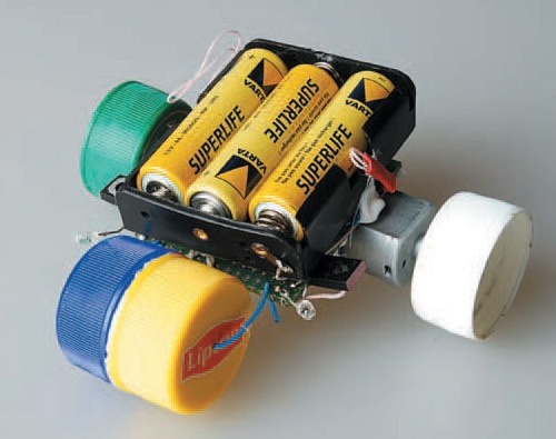
Our simple robot
Many of us who encountered computer technology dreamed of assembling a robot. For this device to perform some duties at home, for example, bring beer. All at once take on the creation of the most complex robot, but often quickly break off in the results. We didn’t bring to mind our first robot, which was supposed to make a crush of chips. For this you need to start with a simple, gradually complicating your beast. Now we will tell you how from the available tools that each house has, you can create a simple robot that will move independently around your apartment.
')
Concept
We set ourselves a simple task, to make a robot in 15 minutes from improvised means. Looking ahead, I will say that we managed, of course, not by fifteen minutes, but by a much longer period. But still it can be done in one evening.
Usually these crafts are made over the years. People are shopping in search of the right gear for several months. But we immediately realized - this is not our way! By this we will use in the design such details that can be easily found at hand, or rooted out from the old technology. As a last resort, buy for pennies at any radio store or on the market.
Another idea was to make our crafts as cheap as possible. Such a robot is in electronic stores worth from 800 to 1500 rubles! What does it sell in the form of parts, and you still have to collect it, and not the fact that after that it will also work. Manufacturers of such kits often forget to put some parts and that's it - the robot is lost along with the money! Why do we need such happiness? Our robot should be no more expensive than 100-150 rubles, including engines and batteries. At the same time, if you pick out the motors from an old children's car, then its price will generally be about 20-30 rubles! You feel what a savings, while you get a great comrade.
The next part was what our handsome man would do. We decided to make a robot that will search for sources of light. If the light source turns, then our machine will steer after it. This concept is called - the robot seeks to live. It is possible he will have to replace the batteries with solar cells and then he will look for the light to drive.
Necessary parts and tools
What do we need for the manufacture of our child? Since the concept of improvised means, then we need a circuit board, or even the usual thick cardboard. In the carton you can use an awl to make holes for fastening all the details. We will use the installer, because it was at hand, and you will not find cardboard in my house during the day. This will be the chassis on which we will mount the rest of the robot, fix the engines and sensors. As a driving force, we will use three or five-volt motors that can be picked out from the old typewriter. The wheels will be made of plastic bottle caps, for example, from sausol.

Some sources
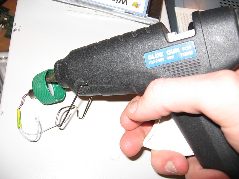
Three-volt phototransistors or photodiodes are used as sensors. They can be picked out even from an old optomechanical mouse. There are infrared sensors in it (in our case they were black). There they are paired, that is, two photocells in one bottle. With the tester, nothing prevents to find out which leg is intended for. The control element will be the domestic transistors 816G. We use three finger-type batteries soldered to each other as power sources. Or you can take the battery compartment from the old typewriter, as we did. For the installation will be necessary wiring. For these purposes, ideal wires from twisted pair, which in the house of any self-respecting hacker should be heaps. For fixing all the parts it is convenient to use hot melt glue. This beautiful invention quickly melts and sets just as quickly, which allows you to quickly work with it and mount simple elements. Stuck is ideal for such crafts and I have used it more than once in my articles. We will also need a hard wire, the usual paper clip will completely fall for it.
We mount the scheme
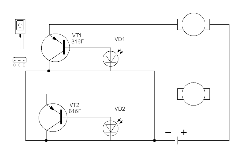
Schematic diagram of the robot
So we got all the details and put them on our desk. The soldering iron is already smoldering with rosin and you are rubbing your hands with a thirst for assembly, well, then let's get started. Take a piece of montage and cut it to the size of the future robot. For cutting PCB use scissors for metal. We made a square with a side of about 4–5 cm. The main thing is that our meager schema fits on it, two batteries for the power supply and fixtures for the front wheel. So that the board is not shaggy and smooth, you can process it with a file, and also remove sharp edges. The next step will be sealing the sensors. Phototransistors and photodiodes have plus and minus, in other words, an anode and a cathode. It is necessary to observe the polarity of their inclusion, which is easy to determine with a simple tester. In case you make a mistake, nothing will burn, but the robot will not drive. The sensors are soldered to the corners of the circuit board on one side so that they look sideways. They should not be fully sealed to the board, but left somewhere around one and a half centimeters of conclusions so that they can be easily bent in any direction - in the future we will need this when setting up our robot. These will be our eyes, they should be on the same side of our chassis, which in the future will be the front of the robot. It can be immediately noted that we collect two control circuits: One for controlling the right and second for the left engines.

Soldered photo sensors and transistors
A little away from the front edge of the chassis, next to our sensors, you need to solder the transistors. For convenience of sealing and assembling of the further scheme, we soldered both transistors with our “markings” towards the right wheel. Immediately it should be noted the location of the legs of the transistor. If you take the transistor in hand, and turn the metal backing towards you, and the marking to the forest (like in a fairy tale), and the legs are pointing down, then from left to right, the legs will be: base, collector and emitter. If you look at the diagram where our transistor is shown, then the base will be a wand perpendicular to a thick segment in a circle, an emitter is a wand with an arrow, a collector is the same wand, but without an arrow. Here everything seems to be clear. Prepare the batteries and proceed to the immediate assembly of the electrical circuit. Initially, we just took three finger batteries and soldered them sequentially. You can immediately insert them into a special holder for batteries, which, as we have said, is pulled out of the old children's car. Now we solder the wires to the batteries and determine on our board two key points where all the wires will converge. It will be plus and minus. We made it simple - we twisted the twisted pair into the edges of the board, soldered the ends to the transistors and photosensors, made a twisted loop and soldered the batteries there. Perhaps not the best option, but the most convenient. Well, now we prepare the wires, and proceed to the assembly of our robot electricians. We will go from the positive pole of the battery to the negative contact, throughout the electrical circuit. We take a piece of twisted pair, and start to go - solder the positive contact of both photosensors to the plus of the batteries, in the same place we solder the emitters of the transistors. Solder the second leg of the photocell with a small piece of wire to the base of the transistor. The remaining, last legs transyuka solder, respectively, to the engines. The second contact of the motors can be soldered to the battery through the switch.
But as true Jedi, we decided to turn on our robot by soldering and soldering the wire, because there was no switch of the right size in my bins.
Electrician debugging
Everything, we have assembled the electrical part, now we will start testing the circuit. Turn on our scheme, and bring it to the lit table lamp. Take turns turning one or another photocell. And watch what happens. If our engines start to rotate in turns at different speeds, depending on the lighting, then everything is fine. If not, look for the shoals in the assembly. Electronics is the science of contacts, which means that if something does not work, then somewhere there is no contact. An important point: the right photo sensor is responsible for the left wheel, and the left one, respectively, for the right one. Now, we pretend in which direction the right and left engine rotates. They should both turn forward. If this does not happen, then you need to change the polarity of turning on the engine, which is spinning in the wrong direction, simply by soldering the wires at the terminals of the motor vice versa. We evaluate once again the location of the motors on the chassis and check the direction of movement in the direction where our sensors are installed. If everything is in order, then we will go further. In any case, this can be corrected, even after everything is finally assembled.
Build device
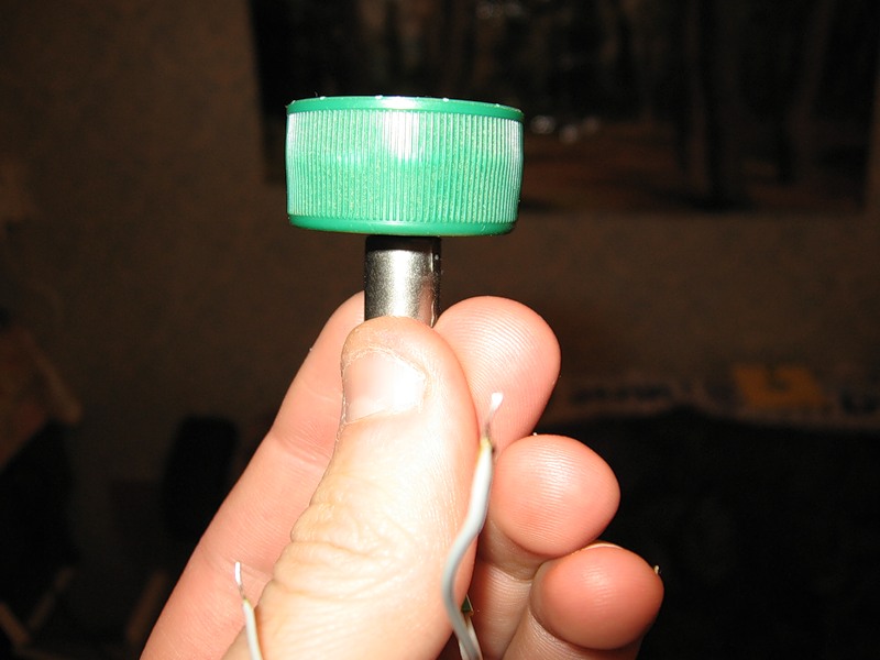
With the dreary electrical part, we figured out, now proceed to the mechanics. We will manufacture the wheels of the caps, from plastic bottles. For the manufacture of the front wheel, take the two covers, and glue them together.
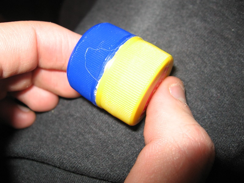
Future front wheel
We glued around the perimeter of the hollow part inside, for greater stability of the wheel. Further, precisely in the center of the lid, we drill a hole in the first and second lids. For drilling and all sorts of home crafts it is very convenient to use a Dremel, a sort of small drill with a variety of nozzles, milling, cutting and many others. It is very convenient to use it for drilling holes less than one millimeter, where even a regular drill cannot cope.
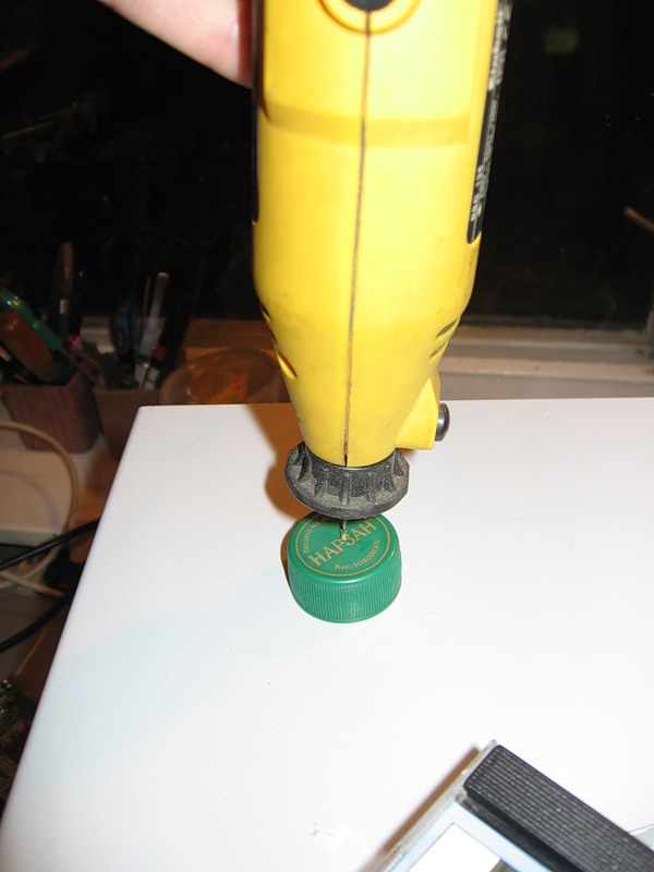
Drilling holes for the axis
After we drill the caps, we insert a pre-unfolded clip into the hole.

Clip, CEP - the basis of the front chassis
Bend the clip in the shape of the letter "P", where the wheel dangles on the upper bar of our letter.

Bend the clip
Now we fasten this clip between photo sensors, in front of our car. The clip is convenient because you can easily adjust the height of the front wheel, and we will deal with this adjustment later.
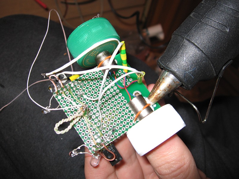
We turn to the driving wheels. We will also make them from covers. Similarly, we drill through each wheel strictly in the center. It is best to drill the size of the axis of the motor, and ideally - a fraction of a millimeter smaller, so that the axis is inserted there, but with difficulty. We dress both wheels on the engine shaft, and so that they do not jump off, we fix them with hot melt.
Fix the axis with hot melt
Ready wheel
It is important to do this not only so that the wheels do not fly off while moving, and also do not turn in place of fasteners.
The most important part is the mounting of electric motors. We put them at the very end of our chassis, on the opposite side of the circuit board, relative to the rest of the electronics. It must be remembered that the controlled engine is placed with opposite to its control photo system. This is done so that the robot can turn on the light. Right photosensor, left engine and vice versa. To begin, we intercept them with twisted pair pieces, threaded through the holes in the assembly and twisted from above.
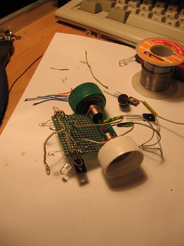
Pilot version of the robot, check the assembly
We supply power, and we look where our engines rotate. In the dark room, the engines will not rotate, it is desirable to direct the lamp. Check if all the engines are working. We rotate the robot and watch how the engines change their rotational speed depending on the lighting. Turn the right photosensor, and the left engine should be smartly spin, and the other one on the contrary, slow down. Lastly, we check the direction of rotation of the wheels so that the robot goes forward. If everything works, as we have described, then you can neatly fix the sliders with hot melt.
Wheel fixing
We are trying to make their wheels on the same axis. All - we fix the batteries on the top of the chassis and go to the settings and games with the robot.
Pitfalls and tuning
The first pitfall in our craft was unexpected. When we put together the whole scheme and the technical part, all the engines responded perfectly to the light, and everything seemed to be going great. But when we put our robot on the floor - he did not go with us. It turned out that the power of the motors is simply not enough. I had to urgently raskruchivat baby machine to get from there engines more powerful. By the way, if you take the motors from the toys, you will definitely not get lost with its power, as they are designed to carry a lot of cars with batteries. When we figured out the engines, we moved on to setting up and driving a cosmetic look. First you need to collect the beards of wires that we drag on the floor, and strengthen them on the chassis with hot glue.

Finishing touches and adjustment
If the robot is dragged somewhere in the belly, then you can lift the front chassis by bending the securing wire. The most important photo sensors. It is best to bend them looking to the side at thirty degrees from the main course. Then he will catch the sources of light, and go to them. The desired bending angle will have to be chosen experimentally. Everything, we arm ourselves with a desk lamp, put the robot on the floor, turn it on and start checking and rejoicing at how your child clearly follows the source of light, and how he deftly finds it.
Enhancements
There is no limit to perfection and you can add functions to infinity in our robot. There were thoughts even to put a controller, but then the cost and complexity of manufacturing would increase by several times, and this is not our method.
The first improvement is to make a robot that would travel along a given path. Everything is simple here, a black stripe is printed on the printer, or similarly it is drawn with a black permanent marker on a sheet of drawing paper. The main thing is that the strip was a bit narrower than the width of sealed photo sensors. We lower the photo cells down so that they look at the floor. Next to each of our eyes, we install a super-bright LED in series with a resistance of 470 Ohms. The LED itself with resistance is soldered directly to the battery. The idea is simple, from a white sheet of paper the light is perfectly reflected, it hits our sensor and the robot goes straight. As soon as the beam hits the dark strip, light almost does not get on the photocell (black paper perfectly absorbs light), and therefore one engine starts to rotate more slowly. Another motor briskly turns the robot, leveling the course. As a result, the robot rolls on a black strip, as if on rails. You can draw such a strip on the white floor and send the robot to the kitchen for a beer from your computer.
The second idea is to complicate the circuit by adding two more transistors and two photosensors and make the robot search for the light not only from the front, but from all sides, and as soon as it was found, it rushed towards it. Everything will only depend on which side the light source will appear: if it is in front, it will go forward, and if it is behind, it will roll backwards. It is possible even in this case to simplify the assembly, use the LM293D chip, but it costs about a hundred rubles. But with the help of it, you can easily adjust the differential inclusion of the direction of rotation of the wheels or, more simply, the direction of movement of the robot: forward and backward.
The last thing you can do is remove permanently sitting-up batteries altogether and put in a solar battery, which you can now buy in the mobile phone accessories store (or on dial-up). In order to prevent the robot from completely losing its capacity in this mode, if it accidentally drops into the shade, it is possible to connect parallel to the solar battery - an electrolytic capacitor of very large capacity (thousands of microfarads). Since the voltage we have there does not exceed five volts, then the capacitor can be designed for 6.3 volts. Such a capacity and such voltage it will be quite miniaturized. Conders can either be bought, or uprooted from old power supplies.
The remaining possible variations, we think, you can think of yourself. If there is something interesting - be sure to write.
findings
So we got to know the greatest science, the engine of progress - cybernetics. In the seventies of the last century it was very popular to design such robots. It should be noted that in our creation applied the beginnings of analog computing, which died out with the advent of digital technology. But as I showed in this article - not everything is lost. I hope we will not dwell on the design of such a simple robot, but we will invent new and new designs, and will surprise us with our interesting crafts. Good luck in the assembly!
This article in a slightly different version was published in Hacker's 109 issue and I was thinking a lot of the time whether to post or not to post it on Habré. But I did decide, I do not like the layout in the magazine, so I decided to publish it with other photos, a little different text, rewritten and adapted for Habr.
With regret, I can say that there is no video of the work of the robot, just as the robot itself is already alive. So be content to have only photos.
Source: https://habr.com/ru/post/120480/
All Articles