DIY Quadcopter: Part II.1
ATTENTION, the article is outdated, but it can still be used for informational purposes.
In the last article I talked about a set of parts for building my quadrocopter, and now it’s time to talk about sensors and brains.
The easiest option is to buy a ready-made shawl with 4 main sensors (9 DOF ):
Just now another shawl appeared, on which, besides the four sensors, there is a GPS receiver , which is useful for autonomous flight.
If you decide to buy just such a board with sensors (then you made the right choice!), Then you can not read about the sensors, but if suddenly you already have at least a gyroscope with an accelerometer or want to play with luck when ordering Wii Motion Plus from Chinese stores, then read this part of the article to the end.
Maybe you recently bought a Wii Motion Plus for your game console from sites like dealextreme or buyincoins , then open it and see which gyro chip is used there, most likely it will be ITG3205, aka ITG3200:
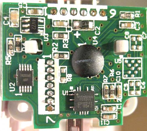
I will use the image from the forum http://forum.xufo.net/bb/viewtopic.php?p=171796
If your board looks like this, then you are very lucky and the next step is to finish this WMP to a good gyro:
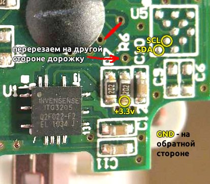
red indicates the place of cutting the track, there is also a track leading to the chip on the reverse side, we also saw it through and on the reverse side there is a convenient place for soldering the GND wiring (ground, common)
And here it is already harder and easier at the same time, I was lucky and the kind user from the rcdesign.ru forum soldered my BMA020 to a handkerchief with minimal strapping, which I put on a thin 2-sided adhesive tape:
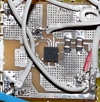
You can search for a separate sensor and independently make a similar scarf or ask friends or buy a finished one with a BMA020 or BMA180 sensor.
')
In fact, any available gyroscope with an accelerometer with an I2C bus will do , but you will have to rewrite the relevant parts of the code or insert the already prepared code from the MultiWii project, for example, for the L3G4200D gyroscope or the adxl335 analog accelerometer. But sometimes you have to tinker with the orientation of the axes of the sensors (change the signs and axes in the code) and the fight against vibration.
For ease of installation, everything you need can be placed on some kind of prototyping shawl, for example, I did it like this (not nice, but it works, the connection module from the previous project is not used to the left above):

The pinout of the connection may be slightly different, since the firmware periodically changes, but at the time of this writing, the motors, sensors, receiver, etc. should be connected as follows (from release note):
This part of the article may become irrelevant, so watch the thread of the forum ArduCopter Mega: port on a regular Arduino (test)
After a successful download of the sketch firmware to Arduino, you can download the setup program (attention, it works only in Windows and is very crooked in Linux with Wine) and close the A5 contact with GND.
After starting the program in the Options menu, select the Arduino COM port:

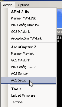
In the Action menu, select AC2 Setup
And we see a huge button that you need to click and follow the instructions. It is especially important not to miss the first window with a bunch of text, in which you will be asked to move the console handles to their minimum and maximum values, as well as another window, in which you will be asked to make sure that The copter stands flat for calibrating the sensors.
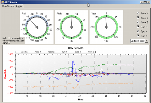
After completing the settings, you can open A5 from GND and select the AC2 Sensor item in the menu to check the adequacy of the sensors in the Raw Sensor tab: turns the sensors with sensors should be clearly worked out - both the arrow was turned and the arrow got up, if it swims or flies over, There are problems with sensors or coefficients in your code.
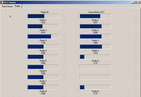
It is also worth checking the receiver in the next tab and if the levels move as it should, then turn the gas joystick (in Mode 2 remote left) down to the right for 2 seconds (I hope at this stage you do not have a battery connected and there are no propellers) the LED on the controller should start flashing. And now slowly move the throttle stick up, while in the left column, the levels should be about the same increase.
Well, everything seems to be all =) Now you can fasten the propellers (do not confuse where, what rotation and check that the motors turn in the right direction) and try to take off, for this, put the copter away from yourself (or hold it in your hand over your head) tilt the left knob down and to the right for 2 seconds and slowly add gas. If the copter takes off - this is already good, if it starts to shake, then you need to adjust the PIDs . To do this, select the PID Config - AC2 item in the Action menu, be horrified by the number of digits and start adjusting the values to suit yourself. I can’t talk about how to do this, as it was done almost by typing, but it’s worth starting with parameter P. I fly well with these settings:

After landing, do not forget to turn off the motors by turning the left joystick knob down and to the left for the same 2 seconds and make sure that the status LED does not flash anymore.
Good luck in assembling and setting up your copter and do not forget to read about new chips on the forum .
Perhaps the next article will be about a fully autonomous flight, but not earlier than in a month, watch your habranth.
In the last article I talked about a set of parts for building my quadrocopter, and now it’s time to talk about sensors and brains.
Sensors and their acquisition methods
The easiest option is to buy a ready-made shawl with 4 main sensors (9 DOF ):
- gyroscope - to measure the angular acceleration
- accelerometer - to measure acceleration and gravity (in fact, you can find out the angle of inclination)
- barometer - for measuring height and keeping the copter at this very height
- magnetometer (compass) - to keep the direction of movement
Just now another shawl appeared, on which, besides the four sensors, there is a GPS receiver , which is useful for autonomous flight.
If you decide to buy just such a board with sensors (then you made the right choice!), Then you can not read about the sensors, but if suddenly you already have at least a gyroscope with an accelerometer or want to play with luck when ordering Wii Motion Plus from Chinese stores, then read this part of the article to the end.
We get the ITG3200 gyroscope
Maybe you recently bought a Wii Motion Plus for your game console from sites like dealextreme or buyincoins , then open it and see which gyro chip is used there, most likely it will be ITG3205, aka ITG3200:
I will use the image from the forum http://forum.xufo.net/bb/viewtopic.php?p=171796
If your board looks like this, then you are very lucky and the next step is to finish this WMP to a good gyro:
red indicates the place of cutting the track, there is also a track leading to the chip on the reverse side, we also saw it through and on the reverse side there is a convenient place for soldering the GND wiring (ground, common)
We get the accelerometer BMA020 or BMA180
And here it is already harder and easier at the same time, I was lucky and the kind user from the rcdesign.ru forum soldered my BMA020 to a handkerchief with minimal strapping, which I put on a thin 2-sided adhesive tape:
You can search for a separate sensor and independently make a similar scarf or ask friends or buy a finished one with a BMA020 or BMA180 sensor.
')
Other sensor options
In fact, any available gyroscope with an accelerometer with an I2C bus will do , but you will have to rewrite the relevant parts of the code or insert the already prepared code from the MultiWii project, for example, for the L3G4200D gyroscope or the adxl335 analog accelerometer. But sometimes you have to tinker with the orientation of the axes of the sensors (change the signs and axes in the code) and the fight against vibration.
Brain building
For ease of installation, everything you need can be placed on some kind of prototyping shawl, for example, I did it like this (not nice, but it works, the connection module from the previous project is not used to the left above):
The pinout of the connection may be slightly different, since the firmware periodically changes, but at the time of this writing, the motors, sensors, receiver, etc. should be connected as follows (from release note):
| Motors (top view, in front of the copter at the top, the direction of rotation and the corresponding propellers can be viewed on this picture or this one ) | |
|---|---|
| Front left | 2 |
| Front right | five |
| Rear left | 6 |
| Rear right | 3 |
| Receiver (at least the first 4, you can take the connector from the IDE cable and cut off the excess to insert into the receiver) | |
| Throttle | A8 |
| Roll | A9 |
| Pitch | A10 |
| Yaw | A11 |
| Mode (Aux1) | A12 |
| Aux2 | A13 |
| Cam1 | A14 |
| Cam2 | A15 |
| Brain and receiver power | |
| Arduino can be powered from the speed controller (if it has a power converter), by soldering the power output to USB and Vin, another option is to power directly from the battery through a special power connector on the board | |
| The receiver is powered from the Arduino through the corresponding outputs + 5v and GND | |
| Other | |
| Switch to command line mode (aha, will be console) and settings for convenience, you can put a jumper or switch | A5 short circuit with GND |
| GPS module | RX2, TX2 |
| Xbee module | RX3, TX3 |
| Sonar / range finder | 9 - tx, 10 - echo |
| LEDs (do not forget about the resistors in series) | 13,30,31 |
Firmware setup and download
This part of the article may become irrelevant, so watch the thread of the forum ArduCopter Mega: port on a regular Arduino (test)
- Download the archive with the firmware and unpack
- The libraries folder should be copied over (with replacement) to the same folder in the Arduino IDE (arduino-0022)
- In the libraries / AP_ADC folder in the AP_ADC_ADS7844.cpp file, select the sensor type: uncomment one of the options #define FFIMU, #define ALLINONE, or simultaneously #define ALLINONE and #define BMA_020 for the version with sensors ITG3200 and BMA020
- If you do not have a barometer (like mine), then you will have to comment out the I2C bus code with this sensor in the libraries / APM_BMP085 / APM_BMP085.cpp file
- Open through the Arduino IDE any of the files in the MegaPirate folder
- In the APM_Config.h tab, select your type of copter, to do this, after #define FRAME_CONFIG, insert one of the options: QUAD_FRAME TRI_FRAME HEXA_FRAME Y6_FRAME OCTA_FRAME, as well as the orientation type of the frame #define FRAME_ORIENTATION, setting PLUS PLUS or X_FRAME
- If you do not have GPS, it is better to change the #define GPS_PROTOCOL value to GPS_PROTOCOL_NONE at the beginning, so as not to wait 10-15 seconds for GPS to initialize (when it is not there!)
- Now you can connect the Arduino Mega and download this sketch to the controller
Setting up the copter
After a successful download of the sketch firmware to Arduino, you can download the setup program (attention, it works only in Windows and is very crooked in Linux with Wine) and close the A5 contact with GND.
After starting the program in the Options menu, select the Arduino COM port:
In the Action menu, select AC2 Setup
And we see a huge button that you need to click and follow the instructions. It is especially important not to miss the first window with a bunch of text, in which you will be asked to move the console handles to their minimum and maximum values, as well as another window, in which you will be asked to make sure that The copter stands flat for calibrating the sensors.
After completing the settings, you can open A5 from GND and select the AC2 Sensor item in the menu to check the adequacy of the sensors in the Raw Sensor tab: turns the sensors with sensors should be clearly worked out - both the arrow was turned and the arrow got up, if it swims or flies over, There are problems with sensors or coefficients in your code.
It is also worth checking the receiver in the next tab and if the levels move as it should, then turn the gas joystick (in Mode 2 remote left) down to the right for 2 seconds (I hope at this stage you do not have a battery connected and there are no propellers) the LED on the controller should start flashing. And now slowly move the throttle stick up, while in the left column, the levels should be about the same increase.
Result
Well, everything seems to be all =) Now you can fasten the propellers (do not confuse where, what rotation and check that the motors turn in the right direction) and try to take off, for this, put the copter away from yourself (or hold it in your hand over your head) tilt the left knob down and to the right for 2 seconds and slowly add gas. If the copter takes off - this is already good, if it starts to shake, then you need to adjust the PIDs . To do this, select the PID Config - AC2 item in the Action menu, be horrified by the number of digits and start adjusting the values to suit yourself. I can’t talk about how to do this, as it was done almost by typing, but it’s worth starting with parameter P. I fly well with these settings:
After landing, do not forget to turn off the motors by turning the left joystick knob down and to the left for the same 2 seconds and make sure that the status LED does not flash anymore.
Good luck in assembling and setting up your copter and do not forget to read about new chips on the forum .
A small video of the fall of the copter in the bushes
As well as adequate flight with GoPro on board
Perhaps the next article will be about a fully autonomous flight, but not earlier than in a month, watch your habranth.
Source: https://habr.com/ru/post/120332/
All Articles