IC 555. Practice
Hello. In the last article I wrote about the chip 555, but the article did not have any practical examples at all. So, this topic will be fully devoted to the practical application of the timer 555. The range of applications of the 555 chip has no boundaries. Everything is limited solely by your imagination. The main modes of the 555 chip and their modifications allow us to use it in many devices. On a chip 555 you can make such devices as a timer, an accurate generator, Schmitt trigger. As well as a time delay generator, pulse width modulator, pulse detector, frequency divider. But today I would like to introduce you to such devices as a dark signal device, a metronome and an anti-theft device.

')
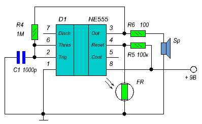
Here is a dark signaling circuit. This scheme will emit a beep when it gets dark. While the photoresistor is lit, at the output №4 is set low, which means that the timer is in reset mode. If there is no illumination, the resistance of the photoresistor increases and a high level appears at the output # 4 and our timer starts. When starting the timer will start to emit a signal.

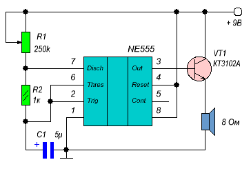
A metronome is a device capable of producing an arbitrary number of clock fractions of time by ear. Most often this device is used by musicians, but I think many people remember the lessons of physics when the teacher turned on this device. The metronome counts the rhythm needed, which can be adjusted by a variable resistor. This scheme is constructed according to the scheme of the generator of rectangular pulses. The frequency of our metronome is determined by the RC-chain (R1, R2 and C1).

This device is an RS-trigger based on the NE555 integrated timer or just 555. To power this device you need only 12 V, which appear when the ignition switch is turned on. An alternative way to power is to use a battery. The device can be connected anywhere, as long as there is power.
The RS flip-flop is set to “on” when the low level initially appears at pin 2 of DA1 due to resistor R2 and capacitor C2. A positive voltage at the output of 3 DA1 switches on the relay K1 to the protection mode and starts charging the capacitor C1 through the resistor R1. Until the voltage on the capacitor C1 has risen to the level of the opening of the transistor VT1, the RS-flip-flop can still be reset with the SA1 control button.
But if VT1 has opened, then a low level is established at input 2, which prohibits resetting the trigger. The voltage on the timer is supplied through a serial diode VD1. As a relay K1, you can use a relay with an operating voltage of 9 V. Contacts K1.1 and K1.2 of the relay K1 can be turned on to block or break any power supply circuit of the vehicle. The removal of this anti-theft device takes place by applying a miniature magnet to contact SA1. I forgot to say that the withdrawal can be made only in the first time (depending on the values of R1 and C1) after the appearance of power.
I do not want to upset you, but this is the end of this article. In the next article I will write about the new schemes, which I find interesting. Try it and you will succeed. Thanks for attention.
Dark signaling device

')
Here is a dark signaling circuit. This scheme will emit a beep when it gets dark. While the photoresistor is lit, at the output №4 is set low, which means that the timer is in reset mode. If there is no illumination, the resistance of the photoresistor increases and a high level appears at the output # 4 and our timer starts. When starting the timer will start to emit a signal.
Metronome

A metronome is a device capable of producing an arbitrary number of clock fractions of time by ear. Most often this device is used by musicians, but I think many people remember the lessons of physics when the teacher turned on this device. The metronome counts the rhythm needed, which can be adjusted by a variable resistor. This scheme is constructed according to the scheme of the generator of rectangular pulses. The frequency of our metronome is determined by the RC-chain (R1, R2 and C1).
Anti-theft device

This device is an RS-trigger based on the NE555 integrated timer or just 555. To power this device you need only 12 V, which appear when the ignition switch is turned on. An alternative way to power is to use a battery. The device can be connected anywhere, as long as there is power.
The RS flip-flop is set to “on” when the low level initially appears at pin 2 of DA1 due to resistor R2 and capacitor C2. A positive voltage at the output of 3 DA1 switches on the relay K1 to the protection mode and starts charging the capacitor C1 through the resistor R1. Until the voltage on the capacitor C1 has risen to the level of the opening of the transistor VT1, the RS-flip-flop can still be reset with the SA1 control button.
But if VT1 has opened, then a low level is established at input 2, which prohibits resetting the trigger. The voltage on the timer is supplied through a serial diode VD1. As a relay K1, you can use a relay with an operating voltage of 9 V. Contacts K1.1 and K1.2 of the relay K1 can be turned on to block or break any power supply circuit of the vehicle. The removal of this anti-theft device takes place by applying a miniature magnet to contact SA1. I forgot to say that the withdrawal can be made only in the first time (depending on the values of R1 and C1) after the appearance of power.
the end
I do not want to upset you, but this is the end of this article. In the next article I will write about the new schemes, which I find interesting. Try it and you will succeed. Thanks for attention.
Source: https://habr.com/ru/post/119751/
All Articles