Cable marking
In this article:
Marking makes sense when there are many wires and it is not immediately clear which one goes where. The point may be not only that there are too many of them.
As a rule, in the server (or data center - data processing center) some external channels are connected (Internet, direct cables to other data centers, company branches, etc.), as well as local equipment located in telecommunications cabinets.
')
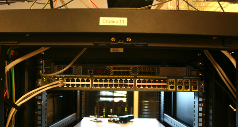
The photo shows the top of such a cabinet. Bottom to the left are suitable cables from other devices in the rack, and cables that go to other racks or to external channels go upwards. Above the racks there is a special organizer for cables.
Inside the rack share the active and passive equipment. Passive serves exclusively for switching purposes. For example, patch panel:

On this panel there are 24 or more ports, it has a height of 1 U or 2U. On the reverse side of the panel, all the cables are bundled, which goes up the rack. As a rule, all ports of one patch panel correspond to ports of another panel in another rack.
Thus, ports in active and passive equipment in various racks are subject to switching.
This table indicates:
It is clear that for equipment in the same rack passive patch panels may be missing. In addition, with different types of connectors, adapters may be present, or the passive equipment itself may be more complicated than a simple panel with ports. If all ports are the same, you can omit it.
In order to effectively designate equipment, it is necessary to introduce some rules of designation.
First, all cabinets / racks within the data center or within several sites created for the common, but spaced geographically, numbered. Since such a cabinet is called a rack, it is designated: R01, R02, etc.
Further, it is convenient to number active equipment from bottom to top by numbers, and passive equipment - from top to bottom by letters A, B, C, etc. Appropriate stickers are applied on the equipment itself or on the side of the rack surface.
Inside the equipment also need to enter the numbering. Many complex devices have modules in them, therefore, in order to use the numbering on them, you first need to specify the module number (always 1 if there are no modules there), and then the port number in it. Ports are numbered from left to right, top to bottom. Port numbering should be transparent, for each type of equipment a numbering picture is needed in the documentation, because when cables are stuck a lot of looking at the digits it is not convenient. I recently met Cisco with inverted (upside down) signs, thanks to the Chinese.
Thus, to designate a specific port, we have something like:R01: 2 \ 1 \ 14 .
For passive equipment it is enough:R03: E-21 , since for one device the numbering will surely be through.
Thus, we have a table of connections from which it is absolutely clear how many cables are needed and which ones, as well as where to plug them.
Marking is needed in order to be able to remove and plug back any cable. In addition, looking at the cable, it is possible to understand where it goes (or at least should go).
What to put on the cable - a matter of taste.
Possible options:
For example, I chose the third option, when on each end of each cable it is written:123 R01: 1 \ 2 \ 12: E-15 , where 123 is the connection number.
Then you can mark the required number of cables and then take them one by one and insert them into the equipment, looking at the marking.
In principle, anything can be used, but it must be borne in mind that ordinary adhesive paper deteriorates due to the server's “weather conditions” and also does not tolerate cable bends. Therefore, the film is better suited, and even better is special. This option will be considered below, but for now - what other options are there?
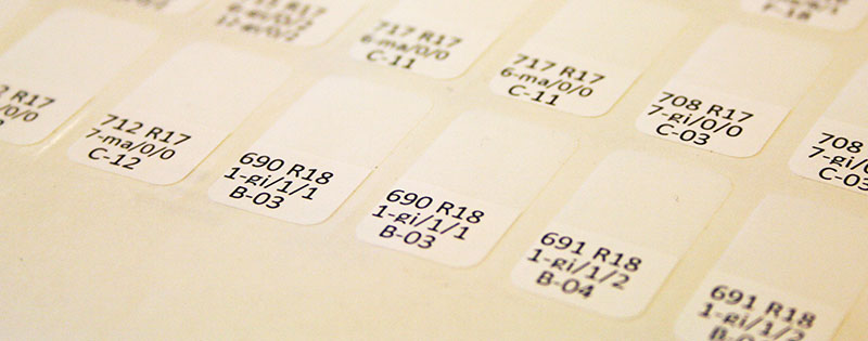
For example, I chose a method with marking on special paper.

On such paper there are separate stickers that are easily peeled off and well glued to the cable. They are called self-laminating, because wrapping the cable starts from the paper part, and then the film (transparent) part is wrapped around the cable and covers the inscription itself, thereby ensuring its durability. Also such paper withstands cable bending, but it is better to glue on a straight piece, it will be smoother.
Print on this paper can be on a conventional laser printer. One sheet in Russian stores, unfortunately, costs from 600 rubles (from 49 to ~ 200 stickers on a sheet, depending on which ones are needed). When ordering in the US prices will be 3-5 times less.
For printing, you need to make a template, the most convenient - in the form of a table in Excel. For paper with 13x10 stickers here is the template: link .
It is necessary to adjust the margins in the template to your printer, since the differences of 1-2 mm affect significantly. You can scan and print this sheet on plain paper and try on it. You can print only on one label, until it becomes the same, but there is a danger that somewhere at the bottom there will still be an offset.
To print, you need to prepare a table with inscriptions for cables. Columns: connection number, inscription on one end, inscription on the other. The inscription may coincide. In my case, I made a breakdown of the inscription into three lines: the connection number and the cabinet, the source equipment, the final equipment. This is a larger font, but there is a big minus: you need to look at the cable from almost 270-degree sides, which is not always easy.
The table is transferred to a template using a VBA macro. The specific macro will differ depending on the template and the table.
R - sheet of the template, S - tables with the initial data.
The result of printing on the very first photo of the article. For 8 hours you can glue off 500-1000 cables.
Used materials:
Pro patch panels
About errors, please write in a personal.
I also accept suggestions about what you would be interested to read from a series of servers and server, telecommunications equipment (Cisco, EMC), servers and blade centers of HP, IBM, Hitachi, etc.
- preparation of the switching table;
- labeling options (what to put on cables);
- review of labeling methods;
- An example of working with one of the methods, including a macro and a template for printing.
What do we commute with?
Marking makes sense when there are many wires and it is not immediately clear which one goes where. The point may be not only that there are too many of them.
As a rule, in the server (or data center - data processing center) some external channels are connected (Internet, direct cables to other data centers, company branches, etc.), as well as local equipment located in telecommunications cabinets.
')
The photo shows the top of such a cabinet. Bottom to the left are suitable cables from other devices in the rack, and cables that go to other racks or to external channels go upwards. Above the racks there is a special organizer for cables.
Inside the rack share the active and passive equipment. Passive serves exclusively for switching purposes. For example, patch panel:
On this panel there are 24 or more ports, it has a height of 1 U or 2U. On the reverse side of the panel, all the cables are bundled, which goes up the rack. As a rule, all ports of one patch panel correspond to ports of another panel in another rack.
Thus, ports in active and passive equipment in various racks are subject to switching.
Preparation of the switching table
This table indicates:
- connection number;
- original active equipment;
- type of connector on the source equipment;
- passive equipment in the same rack;
- final active equipment;
- type of connector on the final equipment;
- active equipment in the same rack;
It is clear that for equipment in the same rack passive patch panels may be missing. In addition, with different types of connectors, adapters may be present, or the passive equipment itself may be more complicated than a simple panel with ports. If all ports are the same, you can omit it.
In order to effectively designate equipment, it is necessary to introduce some rules of designation.
First, all cabinets / racks within the data center or within several sites created for the common, but spaced geographically, numbered. Since such a cabinet is called a rack, it is designated: R01, R02, etc.
Further, it is convenient to number active equipment from bottom to top by numbers, and passive equipment - from top to bottom by letters A, B, C, etc. Appropriate stickers are applied on the equipment itself or on the side of the rack surface.
Inside the equipment also need to enter the numbering. Many complex devices have modules in them, therefore, in order to use the numbering on them, you first need to specify the module number (always 1 if there are no modules there), and then the port number in it. Ports are numbered from left to right, top to bottom. Port numbering should be transparent, for each type of equipment a numbering picture is needed in the documentation, because when cables are stuck a lot of looking at the digits it is not convenient. I recently met Cisco with inverted (upside down) signs, thanks to the Chinese.
Thus, to designate a specific port, we have something like:
For passive equipment it is enough:
Thus, we have a table of connections from which it is absolutely clear how many cables are needed and which ones, as well as where to plug them.
What to put on the cable?
Marking is needed in order to be able to remove and plug back any cable. In addition, looking at the cable, it is possible to understand where it goes (or at least should go).
What to put on the cable - a matter of taste.
Possible options:
- connection number;
- at the port of passive equipment indicate active (in the same rack), and for the active port - active in the same rack. It is convenient for the concept of where this cable leads, but it is impossible to insert it into the necessary port without a table, it can be used for marking after switching;
- writing the same thing at both ends: the rack number and which two ports the cable connects to it, it’s convenient for pre-marking, but you won’t understand where the cable leads without a table, especially if the corresponding patch panels are not indicated;
- others.
For example, I chose the third option, when on each end of each cable it is written:
Then you can mark the required number of cables and then take them one by one and insert them into the equipment, looking at the marking.
Overview of labeling methods
In principle, anything can be used, but it must be borne in mind that ordinary adhesive paper deteriorates due to the server's “weather conditions” and also does not tolerate cable bends. Therefore, the film is better suited, and even better is special. This option will be considered below, but for now - what other options are there?
- Special tags ;
- the usual marker, the number can be written directly on the cable;
- You may be asked to label the cable manufacturers if the order goes directly to the factory;
- equipment that prints the label itself (video work on the link);
- typesetting rings .
Example
For example, I chose a method with marking on special paper.
On such paper there are separate stickers that are easily peeled off and well glued to the cable. They are called self-laminating, because wrapping the cable starts from the paper part, and then the film (transparent) part is wrapped around the cable and covers the inscription itself, thereby ensuring its durability. Also such paper withstands cable bending, but it is better to glue on a straight piece, it will be smoother.
Print on this paper can be on a conventional laser printer. One sheet in Russian stores, unfortunately, costs from 600 rubles (from 49 to ~ 200 stickers on a sheet, depending on which ones are needed). When ordering in the US prices will be 3-5 times less.
For printing, you need to make a template, the most convenient - in the form of a table in Excel. For paper with 13x10 stickers here is the template: link .
It is necessary to adjust the margins in the template to your printer, since the differences of 1-2 mm affect significantly. You can scan and print this sheet on plain paper and try on it. You can print only on one label, until it becomes the same, but there is a danger that somewhere at the bottom there will still be an offset.
To print, you need to prepare a table with inscriptions for cables. Columns: connection number, inscription on one end, inscription on the other. The inscription may coincide. In my case, I made a breakdown of the inscription into three lines: the connection number and the cabinet, the source equipment, the final equipment. This is a larger font, but there is a big minus: you need to look at the cable from almost 270-degree sides, which is not always easy.
The table is transferred to a template using a VBA macro. The specific macro will differ depending on the template and the table.
Public Sub CopyToExcel() ' ' Dim StepV As Long Dim StepH As Long Dim CountH As Long ' ' Dim CurrentH As Long Dim CurrentV As Long ' ' Dim currentL As Long ' ' Dim Say As String Dim Rack As String Dim Patch As String Dim Active As String ' ' StepV = 4 StepH = 2 CountH = 12 currentL = 2 CurrentH = 1 CurrentV = 1 With Sheets("R") While Sheets("S").Cells(currentL, 1) <> "" If Len(Sheets("S").Cells(currentL, 2)) > 0 Then Say = Sheets("S").Cells(currentL, 2) ' Link number ' Rack = Left(Say, 3) Say = Replace(Say, Rack & "=", "") .Cells(CurrentV, CurrentH).Value = Val(Replace(Sheets("S").Cells(currentL, 1), ".", "")) & " " & Rack .Cells(CurrentV, CurrentH + StepH).Value = Val(Replace(Sheets("S").Cells(currentL, 1), ".", "")) & " " & Rack Active = Replace(Left(Say, InStr(Say, "=")), "=", "") Patch = Replace(Say, Active & "=", "") ' First link ' .Cells(CurrentV + 1, CurrentH).Value = Active .Cells(CurrentV + 2, CurrentH).Value = Patch ' Second link ' .Cells(CurrentV + 1, CurrentH + StepH).Value = Active .Cells(CurrentV + 2, CurrentH + StepH).Value = Patch ' New coordinates ' CurrentH = CurrentH + 2 * StepH If CurrentH >= (CountH - 0) * StepH - 1 Then CurrentH = 1 CurrentV = CurrentV + StepV End If ' , - . ' End If currentL = currentL + 1 Wend End With End Sub R - sheet of the template, S - tables with the initial data.
The result of printing on the very first photo of the article. For 8 hours you can glue off 500-1000 cables.
Used materials:
Pro patch panels
About errors, please write in a personal.
I also accept suggestions about what you would be interested to read from a series of servers and server, telecommunications equipment (Cisco, EMC), servers and blade centers of HP, IBM, Hitachi, etc.
Source: https://habr.com/ru/post/119609/
All Articles