Adding Input Method to Arduino
 There are a large number of different master whales for various microcontrollers. However, in the Arduino came up with a model of the master whale with an almost zero threshold of entry. It is enough to enter three lines of code and you already blink the LED or control the engine. But as far as the breadboard model grows, with all sorts of sensors, a display and buttons you begin to understand that there is a lack of a more advanced input method - a keyboard. Not expensive and mobile version is described under the cut.
Part One - Theoretical
There are many methods for connecting the keyboard to the Arduino:
- ordinary matrix keyboards that cling directly to ports ( Keypad Tutorial ). The disadvantage is that it takes a lot of I / O ports, few buttons.
- matrix keyboards connected via I2C ( I2C Port expander and Keypads ). Advantages - takes only two outputs, allows you to use multiple devices on the same bus. Disadvantages - you need to include in the project a library for working with I2C, few buttons
- ordinary PS / 2 keyboard ( PS2 Keyboard ). Advantages - a large hardware base, a bunch of buttons for every taste, it takes few conclusions. Disadvantages - need a library to convert scan codes, size - PS / 2 keyboards do not differ in mobile size
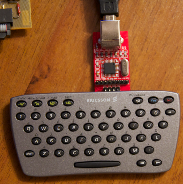
Having rejected all these methods due to the small number of buttons or a large size, I remembered that I had a miniature keyboard for a cell phone on my anthresals for ten years now - Ericsson Chatboard:
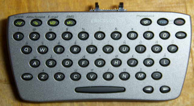
Specifically, this model CHA-01 is rated at 5 volts and seems to be a telephone ... a modem!
There is also the CHA-10 model, which is used with newer (if it can be said about devices of the age of five or seven years old) telephones and operates from 3.3 volts. Both models are not difficult to purchase on EBay for ~ $ 12 with delivery.
You can limit the unmodified version of the keyboard. Search for the connector from the old phone to connect. Develop a library that will parse input from the keyboard, and enjoy life.
However, it will not take long to rejoice - a large protocol overhead (pressing the 0 key causes, for example, 'AT * EKSE = 0', and www - 'AT * EAPP = 0.5, “WWW:”, “WWW”') and switching on the input only after pressing the SMS button do not give ease of use.
')
The way out is to make something different on the basis of this keyboard, which will work as it is necessary for us and with the ability to change the behavior if necessary.
Part Two - Practical
A search on the Internet has given the next page , which I used as the basis for my rework. The most valuable information from there was that the microcontroller in the keyboard and the Atmel Mega162 match the conclusions and the latter can be replaced by the built-in one.
Inside the keyboard is a standard matrix size of 7x7 and occupies 14 pins of the microcontroller. Outside information is issued via UART.
Taking the given information as a basis, we build a plan for reincarnation:
- replace the microcontroller with mega162 ($ 3 on the market)
- replace the connector with “common”
- add the ability to change the software whenever you want (the benefit is realizable through the bootloader)
- set up a normal IDE to work with AVR / Arduino (to get rid of unnecessary here C ++ / libraries)
- write a simple software to test the performance (check IDE settings and familiarization with C for AVR)
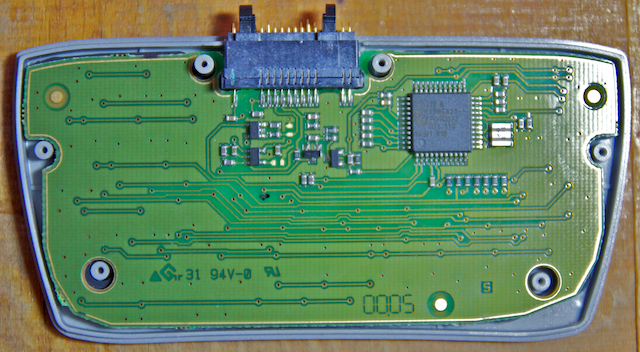
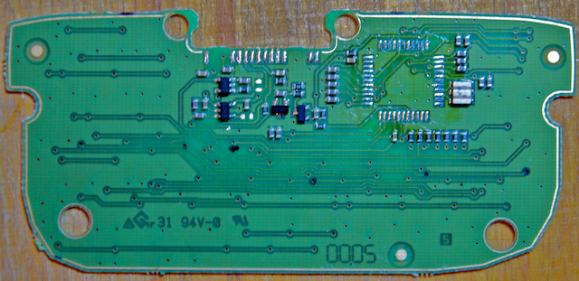
Armed with a soldering station, we remove unnecessary components:
Pinout of the original connector for CHA-01 can be found here :
1, 5 - Vcc +5 Volt
2 - Chatboard serial out
3 - GND
4 - Chatboard serial in
Solder our spare parts:
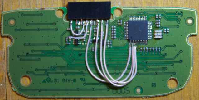
Unlike the author of the above article, I chose the standard PBS-08 line as the connector - it fits perfectly into the case without a file and even lays down the right places on the board. And I decided not to switch to an external resonator.
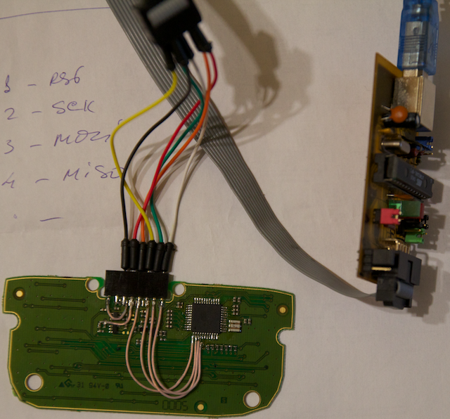
RX, TX, GND, Vcc, MOSI, MISO, SCK and RST were brought to the connector. Thus, we will be able to reprogram the device in the future without removing it from the case.
It seems that everything is ready and can be connected to the programmer (I used to use USBASP, but you can also use arduin to program other AVRs - ArduinoISP )
But avrdude completely refuses to see the microcontroller. As before, I had no experience of such alterations - I had to turn to more experienced comrades for diagnostics. The heavy artillery with the oscillograph and the generator undertook the business. After a short fight, I was sent ... RTFM.
It turns out USBASP works with fast microcontrollers (more than 4 MHz), and mega162 by default includes a “divider by 8” and operates from an internal generator at a frequency of 1 MHz. Since the frequency of 1 MHz for the keyboard is more than enough (and the consumption is less), I decided not to change it and look for ways out of the situation. The way out was found very quickly - USBASP has a jumper that lowers the “frequency of communication” with the microcontroller (or the av option of -B for avrdude, which does it programmatically, helped me -B 3).
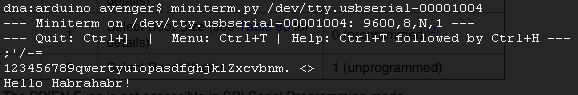
Now, when avrdude sees the crystal, it would seem, it is necessary to reflash and forget :) But the experience of the first RTFM cooled me a little and I decided to drive the software on the emulator first (as it turned out for good reason). To do this, on Proteus experienced comrades, was assembled keyboard layout. And the firmware was written, which interrogated the keyboard and output the required character in the UART. And so, everything is compiled, loaded into the emulator, the parameters of the virtual terminal are set to 9600,8n1. But for some reason, the terminal shows garbage when you press a key. Debug USART mode in the emulator showed that the exchange rate is set at 10200 and not at 9600 ... Again RTFM - Baud rate depends on the chip frequency and at 1 MHz, the standard setting allows you to reach the speed of 4800 (with an error of 0.2%), while at 9600 the error is 7%! The datasheet also contains an error table for various Baudrate / MHz - from where it can be seen that at a frequency of 1 MHz, an error of 0.2% can be achieved only by setting Double-rate USART. In C, it looks like this:
#define F_CPU 1000000UL #define BAUD_RATE 9600UL // Init serial UBRR0L = (uint8_t)(F_CPU/(BAUD_RATE*8L)-1); UBRR0H = ((F_CPU/(BAUD_RATE*8L)-1) >> 8); UCSR0A = _BV(U2X0); // Set double-speed, for low freq cpu UCSR0B = _BV(TXEN0)|_BV(RXEN0); // Enable TX, Enable RX UCSR0C = _BV(URSEL0)|_BV(UCSZ00)|_BV(UCSZ01); // 8n1 async Hurray, our code works fine in the emulator - shows all keystrokes, works out pressing Shift and so on.
Go to the fill software in the keyboard. The bootloader took from the first link ( stk500boot.zip ). Since it also works through USART, it has changed initialization and speed in source code to 9600.
Bootloader via USBASP is flooded with the following command:
avrdude -c usbasp -p m162 -B 3 -U flash:w:stk500boot.hex:i -U hfuse:w:0x98:m
Changing hfuse is necessary to change the reset-vector - so that the microcontroller download starts from the bootloader.
Further communication with the keyboard can be done through the UART, and we will not need USBASP.
I chose a USB-UART (Serial) converter based on FTDI - since the Arduin itself is built on the same chip, so I already have drivers in the system.
By coincidence, the converter connector and my keyboard perfectly matched each other, so I connected it directly:
Despite the statement that this STK500 bootloader is compatible - avrdude did not want to work with it through the type of programmer stk500v1 - cursed that the wrong device ID. From the source it was clear that the bootloader can read and give the device ID, so I found by the brute force method that it works great if I specify the type of arduino.
The command for uploading firmware via UART:
avrdude -c arduino -p m162 -b 9600 -P /dev/tty.usbserial-00001004 -U flash:w:chatboard.hex:i
Checking through the terminal showed that not all buttons are pressed, and the main feature of the bootloader, switching to software update mode by pressing the Yes button, also does not work. It was impossible to flash the keyboard through the UART. A more detailed study showed that three columns of buttons from a 7x7 matrix did not work. Everything again came up against RTFM ... the three pins we used to poll the keyboard also have an alternative function (JTAG) enabled by default. Turning off JTAG (rewrite hfuse to 0xD8) we get a fully functional keyboard:
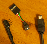 Time to connect to the Arduino. As an interface connector, I chose a non-standard miniUSB, so as not to accidentally plug something inappropriate. The donor for the wire was the old mouse (from where it is still possible to remove the encoder). Connecting to the keyboard is a standard male connector.
The miniUSB - UART adapter was assembled to pinout the UART onto the SensorShield (there is no standardized output for the UART on my breadboard).
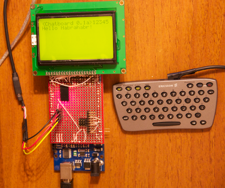
Results
- The keyboard is small enough to carry it with you in your pocket.
- Keyboard polling via UART allows you to work with it without any external libraries (it saves space in the flash)
- Using UART will allow you to further connect the keyboard wirelessly via Bluetooth serial or XBee serial
Ps. The size of the Eclipse + avr-gcc-compatible firmware is only 600 bytes. While the binarica is less than 3k I did not see in the Arduino IDE.
Pps. Sources and firmware can be found here: chatboard.tar.gz
Source: https://habr.com/ru/post/116759/
All Articles