Non-orthogonal bees for small UAVs
According to the rules of abbreviations in the title should not be, but writing abbreviations I would turn the title into an annotation. So here ...
- SINS - free inertial navigation system
- UAV - unmanned aerial vehicle
- RON - sensor sensitivity axis
The article will focus on the navigation system in which the PTS sensors are oriented non-orthogonally, i.e. located at a certain non-zero angle to the axes of the coordinate system associated with the UAV. The peculiarity of such SINS is that according to information from each of the sensors you can get the values of all three components of the angular velocity (for gyroscopes) and linear acceleration (for linear accelerometers) of the object.
The article is written as an addition to Building a multikopter, part two . The goal is to describe one of the ways to deal with zero drift in cheap sensors.
INTRODUCTION
The advantages of BINS are the relative cheapness (it is possible to use sensors from the category of "low cost"), small dimensions and weight, as well as low power consumption. These advantages are particularly well seen in SINS, built on micromechanical navigation sensors (gyroscopes - MMG, accelerometers - MMA).
Blocks of linear micromechanical accelerometers are used as sensors for the apparent acceleration of a moving object as part of inertial navigation systems. They do not have high accuracy characteristics (if we consider inexpensive MMA). However, there are tasks for which they are well suited. For example, in small aircraft the small size and weight, coupled with the low power consumption of MMA blocks, bring many benefits. The same applies to the automotive industry, where they are combined with satellite systems (GPS, GLONASS or others).
One of the serious problems of low-cost micromechanical sensors is the random zero drift. To put it simply, drift is when the sensor indicates that the object is rotating (MMG drift), although in reality there is no rotation. The drift has a constant component, which can be compensated, and a random component, which is difficult to compensate. There are different ways to deal with random error. One of them is the construction of non-orthogonal SINS with information redundancy.
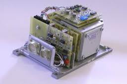
In this article, the story goes on the example of a block of four biaxial MMA ADXL-203CE, PTS which are oriented in parallel forming two cones. The optimum angle of the half-cone for uniaxial meters is 54.75 degrees [1] . For biaxial sensors, it is necessary to apply the PTS arrangement on two cones. This design is described in the patent of the Russian Federation No. 1810299, “Block of inertial sensitive elements with excessive structure”.
EXCESS UNIT
To create information redundancy, it is necessary that the number of measuring channels (sensitivity axes) in the block be more than the number of measured parameters. For a block of 4 biaxial sensors, we get 8 measuring channels, which is quite enough to build a normal SINS. In this case, as mentioned above, the PTS sensors must be oriented parallel to the forming cone. To create such a structure, it is not necessary to make a cone and even a pyramid. The sensors can be placed on the side surface of the parallelepiped and rotate them around the normal to the side face. The following will turn out
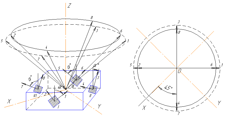
Fig. 1. The design of the redundant unit.
The sensors themselves can be sold being already soldered to mini-boards with mounting holes. The basis for the block can be made from a PCB (plastic, wood, etc.). The accuracy of the mounting holes in the base plays a secondary role. The sensors themselves have an internal orientation error that is large enough. After assembling such a BINS, in any case, it is necessary to calibrate the sensors to determine the actual values of the matrix of cosine guides and scale factors [2] .
For such an orientation of the sensors, it is required to create a matrix of cosine guides. This matrix consists of the cosines of the angles between the POC sensor (rows) and the axes of the object coordinate trihedron (columns). To build a matrix of direction cosines, you can use the method of successive turns [ 3 , 4 ] .
With the above installation of sensors we get the following scheme of turns.
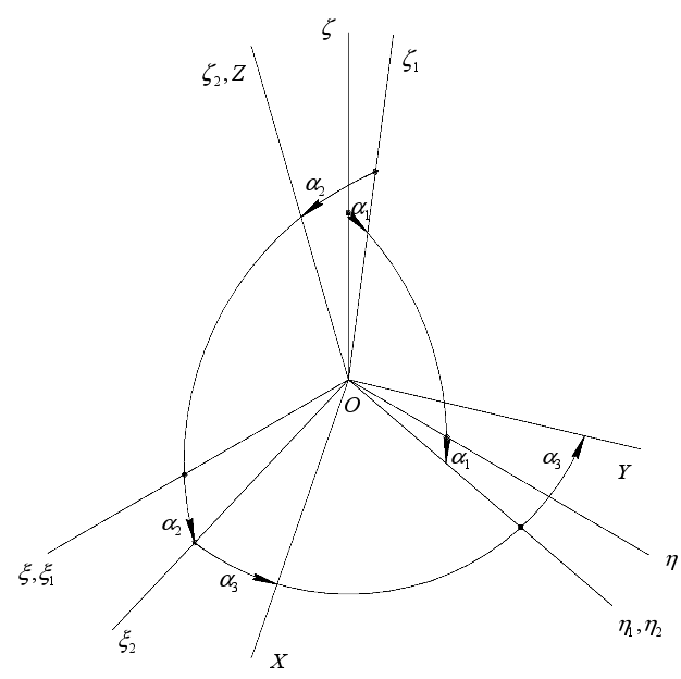
Fig. 2. Scheme of turns of the sensor in the block
In this case, the result will be a matrix [8x3] - eight axes of sensitivity of the sensors and three axes of the associated coordinate system. To check the correctness of compiling the matrix of cosine guides, there are several criteria:
- row vectors of the matrix H have a rate equal to 1
- Any three lines are linearly independent (the requirement that there are no two parallel and three coplanar PSDs in the block)
- matrix (H T * H) -1 - covariance matrix of errors, is diagonal with elements in the diagonal less than one.
For optimal PTS orientation (on the surface of one cone with a half-angle of 54.75 degrees) we have:

This means that for a given PF orientation, the error variance along the OX and OY axes will decrease by the root of 2, and by OZ, by a factor of two [1] .
PROCESSING INFORMATION OUTSIDE BLOCK
In the simplest case, to obtain an estimate of the components of the absolute angular velocity vector (or apparent acceleration), it will be necessary to solve a system of linear algebraic equations (SLAE), in the right-hand sides of which are the output signals of the sensors, independent variables — the desired components of the angular velocity (acceleration) vector, and coefficients — elements cosine guide matrices. Due to information redundancy, the resulting SLAE will be overdetermined (the number of equations is greater than the number of variables). In the general case, such a system of solutions (exact) does not have. For its approximate solution, you can use, for example, a simple algorithm of the Gaussian method of least squares:

Using this expression, the pseudo-inverse of the rectangular matrix is calculated. This method imposes serious restrictions on suppressed noise (zero mean, Gaussian noise, equal to the noise dispersion in different measuring channels).
A little more complicated is the Gaussian-Markov OLS algorithm (weighted least squares method, MVN):

where N is the matrix of direction cosines,
C is the covariance matrix of measuring noise.
From the MVNK, a recurrent Gaussian-Markov OLS is derived, which in [5] is called a Kalman-Bucy filter:


This algorithm does not take into account the dynamic model of sensors.
The following algorithm is a Kalman filter that takes into account the dynamics of the sensors:


In the manual [5], these algorithms are described in detail, in the same place you will find a generalization of the Kalman filter for various particular cases of noise, schemes of the cumulative system “block - observer”.
')
In addition to algorithms based on OLS, you can use, for example, neural networks to solve systems of equations [ 6 ]
CALIBRATION BLOCK
If you use sensors with an analog output, then you need to calibrate the scale factors of the sensors to bring the volts to angular velocity and acceleration. For sensors with digital output (for example, Analog Devices has a micro-mechanic with a SPI interface), the scale factor does not need to be calibrated. You also need to calibrate the matrix of cosine guides, i.e. to determine the real values of the orientation angles of the already mounted block (the base “on the knee” is not to be made exactly, plus the errors of soldering the sensors to the carrier plates and internal non-ideals). You might think that if the sensors are very noisy, then with calibration it makes no sense to bother. However, by calibration, we eliminate the displacement of the average noise. Therefore, calibration is still important.
How to calibrate? For a block of accelerometers this can be done in the field of the Earth. For gyroscopes too, if you know the vertical component of the rotation of the planet at its location.
When working on a diploma, I used a laboratory setup consisting of a redundant unit, ADC, PC, and a turntable.
The main difficulty here is the turntable. I think this device is not for sale in the “Young Technique”. It is also desirable to organize the “mini lab” on the “unleashed” foundation, somewhere far from the highway. As indicated in Building a multi-rotor, part two , MMA is fairly sensitive. If you “rustle” on the table on which the block is placed, then you will see it with the naked eye on the graphs of the output signals.
The scale calibration method may be as follows.
- Make several groups of holes in the edges of the base to fix the board with the sensor at different angles (discreteness, for example, 15 degrees).
- Set the base to the horizon so that the sensor gives the maximum positive value (if the sensor has a zero offset signal, then just the maximum)
- By turning the sensor 15 degrees around the normal to the face, we get several values from maximum to minimum (from + 1g to -1g)
According to the obtained measurements, it is easy to build a trend line, the slope of which will be a scale factor. But it is necessary to take into account that near zero the sensor readings deviate more from the trend.
For an intelligent calibration of the matrix of cosine guides, a turntable is desirable. If there is none, then it is necessary to expose the edge of the MMA block with the sensor being calibrated perpendicular to all three planes of the local coordinate trihedron as accurately as possible, and determine its angles in the base edge from the sensor readings. If you are sure that your base is a parallelepiped, then the task is somewhat simplified.
CONCLUSION
What is the effect of non-orthogonality and redundancy? Because if we struggle with random drift, which can be both positive and negative, then by summing the projections of drifts on the object coordinate axes we will get a decrease in the total measurement drift (of course, with optimal orientation). The effect can be enhanced by orientating one PTS along the cone axis (suitable for an odd number of measuring channels).
Another important effect is increased reliability due to the excessive number of sensors. Failure of the measuring channel will only lead to an increase in measurement error (while 4 or more measuring channels are operating in the unit). Thus, it is possible to construct an algorithm that will adapt to possible malfunctions. In the case of failures, it will not even be necessary to modify the algorithms (to rebuild the matrix of cosine guides), it suffices to supply too much dispersion in the covariance matrices of the MVNK and FC for the failed channel.
BIBLIOGRAPHY
1. Vodicheva LV. Increasing the reliability and accuracy of a strapdown inertial measuring unit with an excessive amount of measurements // Gyroscopy and navigation. 1997. № 1. - p. 55-67.
2. Aleshkin M.V. Mathematical models, methods and algorithms for processing redundant information of the measuring unit / V.V. Aleshkin, AC Matveev, M.V. Aleshkin // Internet and innovations: a collection of works of the Intern. conf. Saratov: SSTU, 2008. p. 377-380.
3. Turning scheme
4. Turn in n-dimensional space
5. Brammer K., Ziffling G. Kalman-Bucy Filter. Deterministic observation and stochastic filtering
6. Neural networks. Solving systems of nonlinear equations
Source: https://habr.com/ru/post/114513/
All Articles