Three-tier network model and technology VLAN, DHCP, OSPF, STP, SNMP, ACL, NTP on Cisco and D-link
This article will help beginners understand how to configure Cisco and D-Link equipment in a three-tier network model. The configuration presented here is not a reference or basic - it is for example and understanding of the essence of things, because Each network solution uses its own parameters and technologies.
Consider the following scheme of a three-level hierarchical model that is used in many network building solutions:
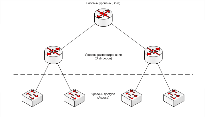
The distribution of network objects by levels occurs according to the functionality that each object performs; this helps to analyze each level independently of the others, i.e. the distribution is mainly not on physical concepts, but on logical ones.
At the kernel level, high-speed and fault-tolerant forwarding of a large amount of traffic is required without the appearance of delays. Here it is necessary to take into account that ACL and non-optimal routing between networks can slow down traffic.
Usually, when there are problems with the performance of the kernel level, you do not have to expand, but upgrade the equipment, and sometimes completely change it to a more productive one. Therefore, it is better to immediately use the best possible equipment without forgetting about the availability of high-speed interfaces with a margin for the future. If several nodes are used, it is recommended to combine them into a ring to provide a reserve.
At this level, routers are used with the configuration principle - VLAN (one or several) per one node of the Distribution level.
Here there is a routing of user traffic between the networks of VLANs and its filtering based on ACL. At this level, the network policy for the end users is described, and the broadcast and multicast mailing domains are formed. Also at this level, static routes are sometimes used to change the routing based on dynamic protocols. Often used equipment with large capacity ports SFP. A large number of ports will provide the ability to connect multiple nodes of the access level, and the SFP interface will give you the choice of using electrical or optical links to a lower level. It is also recommended to unite several knots in a ring.
Switches with routing functions (L2 / 3) and with the principle of configuration are often used: VLAN of each service to one node of Access level.
')
Users themselves physically join the access level.
Often at this level, traffic from user ports is marked with the appropriate DSCP labels.
Here switches L2 (sometimes L2 / 3 +) with the principle of configuration are applied: VLAN services per user port + control VLAN per access device.
When considering the following technologies, Cisco Catalyst equipment is used at the core level and distribution, and D-Link DES for access level. In practice, such a division of brands is often found due to the difference in price, since at the access level, it is generally necessary to install a large number of switches, increasing the capacity of the ports, and not everyone can afford to have these switches as Cisco.
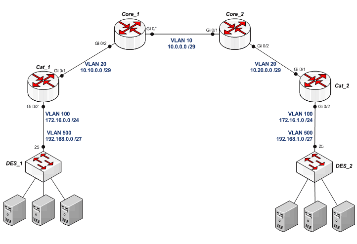
Let's collect the following scheme:

The scheme is simplified to understand the practice: each core includes only one node of the distribution level, and for each such node there is one node of the access level.
In practice, for large scale networks, the meaning of such a structure is that user traffic from multiple access level switches is aggregated at the parent distribution node, routed or switched, as needed, to the higher core, to the neighboring distribution node, or directly between users from different access nodes. And each core routes or switches traffic between several distribution nodes that are directly included in it, or between neighboring cores.
VLAN is a logical division of a network into independent host groups.
Through the use of VLAN, you can do the following things:
Distribute VLANs according to the following scheme:
Let's start with the access level.
On the DES_1 switch (D-Link), let's create a VLAN 100 to manage:
Add it tagged on port 25:
It is better to disable the manager VLAN on ports (1-24) to which users connect:
The default device VLAN will remove:
Put the switch IP address in the management VLAN:
Let's prescribe the gateway, which will be the logical interface of the device at the higher distribution level:
Create a VLAN 500 in which DHCP service is provided (the DHCP server itself will be at the distribution level) and make it untagged on user ports (1-24) and tagged on uplink (25):
On DES_2, all the same settings except the IP address (172.16.1.2) and the gateway (172.16.1.1).
We now turn to the level of distribution.
Configure Cat_1 .
If we use a Catalyst switch, then VLANs are created in configuration mode (
Pre-best VTP switch to transparent mode:
It is necessary to create three VLANs: access point management - VLAN 100, for communication between Cat_1 and Core_1 - VLAN 20 and we have one access node for each distribution level, therefore for the DHCP service one VLAN is created - 500, on a real network it is necessary for each Access switch in its VLAN with DHCP:
Add VLAN 20 to the interface (gi 0/1) to which the kernel is connected.
Enter configuration mode:
Gi 0/1 interface configuration:
Specify the use of the 802.1Q standard:
Put the port into trunk mode:
Add VLAN:
If there are already any VLANs on the port, then you need to use the command:
With the same commands we add VLANs 100, 500 to gi 0/2 to which DES_1 is connected.
To configure several interfaces at once, you can do the following:
Specify the network to control the level of access:
Set the IP for Cat_1 :
We also configure Cat_2 in the same way, only changing the addresses in VLANs 100 and 20. VLAN 100 is 172.16.1.1 255.255.255.0, VLAN 20 is 10.20.0.2 255.255.255.248
On Core_1, create VLANs 10 and 20, add 10 to gi 0/1, where Core_2 is connected and 20 to interface gi 0/2, to which the distribution level node is connected, set the IP addresses: VLAN 10 - 10.0.0.1 255.255.255.248 , VLAN 20 - 10.10.0.1 255.255.255.248.
On Core_2, we also create VLANs 10 and 20, add 10 to gi 0/1, where Core_1 is connected and 20 to the interface gi 0/2, to which Cat_2 is connected, put the IP addresses: VLAN 10 - 10.0.0.2 255.255.255.248, VLAN 20 - 10.20.0.1 255.255.255.248.
DHCP is a client-server protocol for automatically configuring an IP address and other parameters on a network host.
The distribution server will be the DHCP server. In the client VLAN'e 500, we will create a DHCP pool with a network of 192.168.0.0 255.255.255.224 for Cat_1 and 192.168.1.0 255.255.255.224 for Cat_2 .
Configure Cat_1 .
Specify the DHCP pool:
Specify the network from which addresses will be issued:
Specify the default gateway that the DHCP client will receive:
Assign the server dns to the client:
Set the rental time in days:
You can specify the domain name:
After that, we exit the DHCP configuration mode and exclude the ip address of the default gateway from the DHCP pool:
Create a logical interface that will be the default gateway for users.
Create the interface itself:
Put the IP address:
For Cat_2, we do it by analogy, using a network 192.168.1.0 255.255.255.224 in VLAN'e 500
After that, DES_1 and DES_2 users will receive addresses via DHCP.
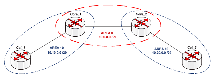
OSPF is a convenient dynamic routing protocol, taking into account the state of the channels. It allows you to create a complete network diagram, and then select the optimal route based on this. Functioning is based on the acquisition of data on the status of network links or channels. A detailed description is in Wikipedia . We will use this particular protocol.
In a real network, each core contains area 0 (for communication with other cores) and several other zones that contain nodes at the distribution level. These nodes within the same zone are conveniently combined into rings, thereby providing reserve and optimal routing. For example, it might look like this:

Define zones in our network:
Configure Core_1 .
Enable routing:
We enable the OSPF process and specify the proccess-id (taken arbitrarily, in our case 111):
Specify the network for each of the zones in which Core_1 is included (it is necessary to use mask inversion):
Usually, you also manually register the Router-id (router ID), indicating the IP address of this router. If you do not do this, then the Router-id will be selected automatically.
On Core_2 we do everything in the same way as on Core_1 .
When configuring Cat_1, we also enable routing and the ospf process with id 111. Specify the network 10.10.0.0 255.255.255.248 in area 10:
You must specify the network redistribution for DHCP (it is in int Vlan500) in this ospf process. This is done by the command:
5 is the metric for the redistributed route
1 is the external metric type - OSPF
After this command, all networks in Cat_1 VLANs will be accessible via ospf.
Redistribution of custom DHCP networks can also be done via the route-map and access-list, or you can specify the entire network xxxx xxxx area x. It all depends on how and what you need to announce in network routing.
We configure Cat_2 in the same way, only in area 10 you need to specify network 10.20.0.0 0.0.0.7
In fact, now we have a working network in which users from different switches of the access level can exchange traffic.
STP is a spanning tree protocol, designed to get rid of unnecessary traffic cycles and is used to build reserves on L2.
The protocol works as follows:
Make a ring of the following form:
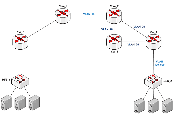
Cat_3 and Cat_2 are in the same area, working on VLAN 20 and connected directly to each other for reserve on L2.
On Core_2 , Cat_2 and Cat_3 we include rapid-pvst. Rapid-Per-VLAN-Spanning Tree allows you to build a tree on each VLAN separately.
We indicate that all existing VLANs must participate in STP with the priority of this node. In order for Core_2 to be the root bridge, it needs to set the priority lower than that of Cat_3 and Cat_2 , which, in turn, may have the same priority.
Core_2 :
Cat_3 :
Cat_2 :
After this, Core_2 will become the root bridge, and one of the ports Cat_3 or Cat_2 will be blocked to send traffic on VLAN 20 to Core_2 . If you need to specify that a specific VLAN does not participate in STP, then this is done with the following command:
It should be noted that the Cisco and D-Link BPDUs with which the STP is built are not compatible with each other, so the stp between the equipment of these two manufacturers will most likely be very difficult to build.
SNMP is a simple network management protocol. With the help of it, statistics of equipment operation is usually collected, and it is often used to automate the performance of any operations on this equipment.
At the nodes of all levels, we define the community, which determines access to the node on read or write using this protocol, provided that this community is the same at the source and the recipient.
On Cisco:
Read -
Write -
The name snmp_community is case sensitive.
On all nodes of the kernel and distribution, we execute these commands:
On D-link:
Delete all default:
Create a community on read - DLINK_READ and on write - DLINK_WRITE:
Access control lists are conditions that are tested when performing any operations.
ACL is used in conjunction with many protocols and network mechanisms, filtering traffic on interfaces and protocols NTP, OSPF and others.
Create a rule to close access from the user network Cat_1 (192.168.0.0 255.255.255.224) to the network Cat_2 , which is located in VLAN'e 500:
As you can see, in the extended access sheets inverse mask is used.
After creating the access list, you need to apply it on the desired interface:
Thereby banning on int vlan500 Cat_2 incoming ip and udp traffic from 192.168.0.0 255.255.255.224 to any address.
Cisco:
Synchronize the internal time of the node with an external server (you can use multiple servers):
Specify time zone (GMT +3):
Start and end daylight saving time:
These commands should be executed on all nodes of the network, or specify the ntp master kernel on the router and the other nodes to synchronize with it.
You can also specify the time manually:
But it is not recommended to do this - it is better to use NTP.
D-Link:
We use SNTP - a simpler version of NTP.
Enable SNTP:
Specify time zone (GMT +3):
Set the NTP server:
Start and end daylight saving time:
We considered the theory of a three-level network model and some basic technologies that will help in the study of such networks.
Theory of Three-Level Model
Consider the following scheme of a three-level hierarchical model that is used in many network building solutions:
The distribution of network objects by levels occurs according to the functionality that each object performs; this helps to analyze each level independently of the others, i.e. the distribution is mainly not on physical concepts, but on logical ones.
Basic Level (Core)
At the kernel level, high-speed and fault-tolerant forwarding of a large amount of traffic is required without the appearance of delays. Here it is necessary to take into account that ACL and non-optimal routing between networks can slow down traffic.
Usually, when there are problems with the performance of the kernel level, you do not have to expand, but upgrade the equipment, and sometimes completely change it to a more productive one. Therefore, it is better to immediately use the best possible equipment without forgetting about the availability of high-speed interfaces with a margin for the future. If several nodes are used, it is recommended to combine them into a ring to provide a reserve.
At this level, routers are used with the configuration principle - VLAN (one or several) per one node of the Distribution level.
Distribution Level
Here there is a routing of user traffic between the networks of VLANs and its filtering based on ACL. At this level, the network policy for the end users is described, and the broadcast and multicast mailing domains are formed. Also at this level, static routes are sometimes used to change the routing based on dynamic protocols. Often used equipment with large capacity ports SFP. A large number of ports will provide the ability to connect multiple nodes of the access level, and the SFP interface will give you the choice of using electrical or optical links to a lower level. It is also recommended to unite several knots in a ring.
Switches with routing functions (L2 / 3) and with the principle of configuration are often used: VLAN of each service to one node of Access level.
')
Access Level
Users themselves physically join the access level.
Often at this level, traffic from user ports is marked with the appropriate DSCP labels.
Here switches L2 (sometimes L2 / 3 +) with the principle of configuration are applied: VLAN services per user port + control VLAN per access device.
Practical application of network technologies in a three-tier model
When considering the following technologies, Cisco Catalyst equipment is used at the core level and distribution, and D-Link DES for access level. In practice, such a division of brands is often found due to the difference in price, since at the access level, it is generally necessary to install a large number of switches, increasing the capacity of the ports, and not everyone can afford to have these switches as Cisco.
Let's collect the following scheme:
The scheme is simplified to understand the practice: each core includes only one node of the distribution level, and for each such node there is one node of the access level.
In practice, for large scale networks, the meaning of such a structure is that user traffic from multiple access level switches is aggregated at the parent distribution node, routed or switched, as needed, to the higher core, to the neighboring distribution node, or directly between users from different access nodes. And each core routes or switches traffic between several distribution nodes that are directly included in it, or between neighboring cores.
VLAN - Virtual Local Area Network
VLAN is a logical division of a network into independent host groups.
Through the use of VLAN, you can do the following things:
- divide one physical device (switch) into several logical levels L2
- if you assign subnets to different VLANs, then the hosts connected to the same device (containing several VLANs) will have different subnets, you can also combine hosts from different devices into the same subnets
- VLAN traffic segmentation leads to the formation of independent broadcast domains, thereby reducing the amount of broadcast traffic on the network as a whole
- Sharing traffic into VLANs also provides security between different networks.
Distribute VLANs according to the following scheme:
Let's start with the access level.
On the DES_1 switch (D-Link), let's create a VLAN 100 to manage:
create vlan 100 tag 100Add it tagged on port 25:
config vlan 100 add tagged 25It is better to disable the manager VLAN on ports (1-24) to which users connect:
config vlan 100 add forbidden 1-24The default device VLAN will remove:
config vlan default delete 1-26Put the switch IP address in the management VLAN:
config ipif System vlan 100 ipaddress 172.16.0.2/24 state enableLet's prescribe the gateway, which will be the logical interface of the device at the higher distribution level:
create iproute default 172.16.0.1 1Create a VLAN 500 in which DHCP service is provided (the DHCP server itself will be at the distribution level) and make it untagged on user ports (1-24) and tagged on uplink (25):
create vlan 500 tag 500
config vlan 500 add untagged 1-23
config vlan 500 add tagged 25
On DES_2, all the same settings except the IP address (172.16.1.2) and the gateway (172.16.1.1).
We now turn to the level of distribution.
Configure Cat_1 .
If we use a Catalyst switch, then VLANs are created in configuration mode (
conf t ) as follows:Vlan < VLAN' >Pre-best VTP switch to transparent mode:
vtp mode transparentIt is necessary to create three VLANs: access point management - VLAN 100, for communication between Cat_1 and Core_1 - VLAN 20 and we have one access node for each distribution level, therefore for the DHCP service one VLAN is created - 500, on a real network it is necessary for each Access switch in its VLAN with DHCP:
Vlan 100,20,500Add VLAN 20 to the interface (gi 0/1) to which the kernel is connected.
Enter configuration mode:
Cat_1#conf tGi 0/1 interface configuration:
Cat_1(config)#int gigabitEthernet 0/1Specify the use of the 802.1Q standard:
Cat_1(config-if)#switchport trunk encapsulation dot1qPut the port into trunk mode:
Cat_1(config-if)#switchport mode trunkAdd VLAN:
Cat_1(config-if)#switchport trunk allowed vlan 20If there are already any VLANs on the port, then you need to use the command:
switchport trunk allowed vlan add < VLAN'> , since if you do not specify add , then existing VLANs will disappear.With the same commands we add VLANs 100, 500 to gi 0/2 to which DES_1 is connected.
To configure several interfaces at once, you can do the following:
Cat_1(config)#int range gigabitEthernet 0/2-3Specify the network to control the level of access:
Cat_1(config)#int Vlan100
Cat_1(config-if)#ip address 172.16.0.1 255.255.255.0
Set the IP for Cat_1 :
Cat_1(config)#int Vlan20
Cat_1(config-if)#ip address 10.10.0.2 255.255.255.248
We also configure Cat_2 in the same way, only changing the addresses in VLANs 100 and 20. VLAN 100 is 172.16.1.1 255.255.255.0, VLAN 20 is 10.20.0.2 255.255.255.248
On Core_1, create VLANs 10 and 20, add 10 to gi 0/1, where Core_2 is connected and 20 to interface gi 0/2, to which the distribution level node is connected, set the IP addresses: VLAN 10 - 10.0.0.1 255.255.255.248 , VLAN 20 - 10.10.0.1 255.255.255.248.
On Core_2, we also create VLANs 10 and 20, add 10 to gi 0/1, where Core_1 is connected and 20 to the interface gi 0/2, to which Cat_2 is connected, put the IP addresses: VLAN 10 - 10.0.0.2 255.255.255.248, VLAN 20 - 10.20.0.1 255.255.255.248.
DHCP - Dynamic Host Configuration Protocol
DHCP is a client-server protocol for automatically configuring an IP address and other parameters on a network host.
The distribution server will be the DHCP server. In the client VLAN'e 500, we will create a DHCP pool with a network of 192.168.0.0 255.255.255.224 for Cat_1 and 192.168.1.0 255.255.255.224 for Cat_2 .
Configure Cat_1 .
Specify the DHCP pool:
Cat_1(config)#ip dhcp pool Vlan500Specify the network from which addresses will be issued:
Cat_1(dhcp-config)#network 192.168.0.0 255.255.255.224Specify the default gateway that the DHCP client will receive:
Cat_1(dhcp-config)#default-router 192.168.0.1Assign the server dns to the client:
Cat_1(dhcp-config)#dns-server <IP_DNS_Server_1> <IP_DNS_server_2>Set the rental time in days:
Cat_1(dhcp-config)#lease 14You can specify the domain name:
Cat_1(dhcp-config)#domain-name workgroup_1After that, we exit the DHCP configuration mode and exclude the ip address of the default gateway from the DHCP pool:
Cat_1(dhcp-config)#ex
Cat_1(config)#ip dhcp excluded-address 192.168.0.1
Create a logical interface that will be the default gateway for users.
Create the interface itself:
Cat_1(config)#int Vlan500Put the IP address:
Cat_1(config-if)# ip address 192.168.0.1 255.255.255.224For Cat_2, we do it by analogy, using a network 192.168.1.0 255.255.255.224 in VLAN'e 500
After that, DES_1 and DES_2 users will receive addresses via DHCP.
OSPF - Open Shortest Path First
OSPF is a convenient dynamic routing protocol, taking into account the state of the channels. It allows you to create a complete network diagram, and then select the optimal route based on this. Functioning is based on the acquisition of data on the status of network links or channels. A detailed description is in Wikipedia . We will use this particular protocol.
In a real network, each core contains area 0 (for communication with other cores) and several other zones that contain nodes at the distribution level. These nodes within the same zone are conveniently combined into rings, thereby providing reserve and optimal routing. For example, it might look like this:
Define zones in our network:
Configure Core_1 .
Enable routing:
Core_1(config)# ip routing
Core_1(config)# ip classless
Core_1(config)# ip subnet-zero
We enable the OSPF process and specify the proccess-id (taken arbitrarily, in our case 111):
Core_1(config)#router ospf 111Specify the network for each of the zones in which Core_1 is included (it is necessary to use mask inversion):
Core_1 (config-router)# network 10.0.0.0 0.0.0.7 area 0
Core_1 (config-router)# network 10.10.0.0 0.0.0.7 area 10
Usually, you also manually register the Router-id (router ID), indicating the IP address of this router. If you do not do this, then the Router-id will be selected automatically.
On Core_2 we do everything in the same way as on Core_1 .
When configuring Cat_1, we also enable routing and the ospf process with id 111. Specify the network 10.10.0.0 255.255.255.248 in area 10:
Cat_1(config)# ip routing
Cat_1(config)# ip classless
Cat_1(config)# ip subnet-zero
Cat_1(config)#router ospf 111
Cat_1(config-router)# network 10.10.0.0 0.0.0.7 area 10
You must specify the network redistribution for DHCP (it is in int Vlan500) in this ospf process. This is done by the command:
Cat_1(config-router)# redistribute connected metric 5 metric-type 1 subnets5 is the metric for the redistributed route
1 is the external metric type - OSPF
After this command, all networks in Cat_1 VLANs will be accessible via ospf.
Redistribution of custom DHCP networks can also be done via the route-map and access-list, or you can specify the entire network xxxx xxxx area x. It all depends on how and what you need to announce in network routing.
We configure Cat_2 in the same way, only in area 10 you need to specify network 10.20.0.0 0.0.0.7
In fact, now we have a working network in which users from different switches of the access level can exchange traffic.
STP - Spanning Tree Protocol
STP is a spanning tree protocol, designed to get rid of unnecessary traffic cycles and is used to build reserves on L2.
The protocol works as follows:
- root bridge is selected on the network
- all non-root nodes calculate the optimal path to the root bridge, and the port (through which this path passes) becomes the root port
- if the path to the root bridge passes through some node, then such a network node becomes designated bridge and the port, respectively, designated port
- ports participating in the stp tree that are not root or designated are blocked
Make a ring of the following form:
Cat_3 and Cat_2 are in the same area, working on VLAN 20 and connected directly to each other for reserve on L2.
On Core_2 , Cat_2 and Cat_3 we include rapid-pvst. Rapid-Per-VLAN-Spanning Tree allows you to build a tree on each VLAN separately.
Cat_1(config)#spanning-tree mode rapid-pvst
We indicate that all existing VLANs must participate in STP with the priority of this node. In order for Core_2 to be the root bridge, it needs to set the priority lower than that of Cat_3 and Cat_2 , which, in turn, may have the same priority.
Core_2 :
Core_2(config)#spanning-tree vlan 1-4094 priority 4096Cat_3 :
Cat_3(config)#spanning-tree vlan 1-4094 priority 8192Cat_2 :
Cat_2(config)#spanning-tree vlan 1-4094 priority 8192After this, Core_2 will become the root bridge, and one of the ports Cat_3 or Cat_2 will be blocked to send traffic on VLAN 20 to Core_2 . If you need to specify that a specific VLAN does not participate in STP, then this is done with the following command:
no spanning-tree vlan <_VLAN'>It should be noted that the Cisco and D-Link BPDUs with which the STP is built are not compatible with each other, so the stp between the equipment of these two manufacturers will most likely be very difficult to build.
SNMP - Simple Network Management Protocol
SNMP is a simple network management protocol. With the help of it, statistics of equipment operation is usually collected, and it is often used to automate the performance of any operations on this equipment.
At the nodes of all levels, we define the community, which determines access to the node on read or write using this protocol, provided that this community is the same at the source and the recipient.
On Cisco:
Read -
snmp-server community <_snmp_community> ROWrite -
snmp-server community <_snmp_community> RWThe name snmp_community is case sensitive.
On all nodes of the kernel and distribution, we execute these commands:
Core_1(config)# snmp-server community CISCO_READ RO
Core_1(config)# snmp-server community CISCO_WRITE RW
On D-link:
Delete all default:
delete snmp community public
delete snmp community private
delete snmp user initial
delete snmp group initial
delete snmp view restricted all
delete snmp view CommunityView all
Create a community on read - DLINK_READ and on write - DLINK_WRITE:
create snmp view CommunityView 1 view_type included
create snmp group DLINK_READ v1 read_view CommunityView notify_view CommunityView
create snmp group DLINK_READ v2c read_view CommunityView notify_view CommunityView
create snmp group DLINK_WRITE v1 read_view CommunityView write_view CommunityView notify_view CommunityView
create snmp group DLINK_WRITE v2c read_view CommunityView write_view CommunityView notify_view CommunityView
create snmp community DLINK_READ view CommunityView read_only
create snmp community DLINK_WRITE view CommunityView read_write
ACL - Access Control List
Access control lists are conditions that are tested when performing any operations.
ACL is used in conjunction with many protocols and network mechanisms, filtering traffic on interfaces and protocols NTP, OSPF and others.
Create a rule to close access from the user network Cat_1 (192.168.0.0 255.255.255.224) to the network Cat_2 , which is located in VLAN'e 500:
Cat_2(config)#ip access-list extended Access_denided_IN
Cat_2(config)#deny ip 192.168.0.0 0.0.0.31 any
Cat_2(config)#deny udp 192.168.0.0 0.0.0.31 any
As you can see, in the extended access sheets inverse mask is used.
After creating the access list, you need to apply it on the desired interface:
Cat_2(config)#int Vlan500
Cat_2(config-if)# ip access-group Access_denided_IN in
Thereby banning on int vlan500 Cat_2 incoming ip and udp traffic from 192.168.0.0 255.255.255.224 to any address.
NTP - Network Time Protocol
Cisco:
Synchronize the internal time of the node with an external server (you can use multiple servers):
ntp server <IP NTP >Specify time zone (GMT +3):
clock timezone MSK 3Start and end daylight saving time:
clock summer-time MSK recurring last Sun Mar 2:00 last Sun Oct 3:00These commands should be executed on all nodes of the network, or specify the ntp master kernel on the router and the other nodes to synchronize with it.
You can also specify the time manually:
clock set 18:00:00 20 Feb 2011But it is not recommended to do this - it is better to use NTP.
D-Link:
We use SNTP - a simpler version of NTP.
Enable SNTP:
enable sntpSpecify time zone (GMT +3):
config time_zone operator + hour 3 min 0Set the NTP server:
config sntp primary <IP NTP _1> secondary <IP NTP _2> poll-interval 600poll-interval is the time interval in seconds between requests for updating SNTP information.Start and end daylight saving time:
config dst repeating s_week 1 s_day sun s_mth 4 s_time 0:3 e_week last e_day sun e_mth 10 e_time 0:3 offset 60We considered the theory of a three-level network model and some basic technologies that will help in the study of such networks.
Source: https://habr.com/ru/post/114406/
All Articles