Building a multikopter, part final
Part 1 | Part 2 | Part 3 | Part 4
The Napoleonic plans described in the previous parts turned out to be practically impracticable by my far from even hands and the scanty forces of two or three people. Therefore, having been inspired by one of the efficient thoughts of the ReWork book, I decided to assemble the flying vehicle. As quickly as possible and with a minimum of effort this time.
')
But it was not there.
Of the huge number of finished projects, I liked German most of all, especially considering that Andrey, the founder and inspirer of the site of a large Russian-speaking community of multicopter enthusiasts , stopped at it. What else will be required details, I approximately described in the previous parts. Putting it all together by adding specifics:
1. Prices are approximate, depending on where and how many parts to take.
2. Depending on how many motors are supposed in the device plus one or two spare ones.
3. Differ in power and additional buns. If I understood correctly, we don’t need additional buns of V2.0 controllers, and the power of V1.2 can be increased by replacing the firmware and mosfets.
4. You will need to buy or solder a PPM converter to it . There is another transmitter, but it is not available.
* - optional part.
Total: $ 1415 - $ 1905.
If you still have some money, you can purchase navigation modules: a magnetic sensor , a navigation card and GPS ($ 90 + $ 170 + $ 112). In fact, the upper price ceiling is practically unlimited. You can order a heavy-duty carbon fiber body, a three-kilogram motor for 20 horsepower and a multikopter rivet capable of lifting hundreds of kg into the air ... But something I dreamed about.
So, suppose the details arrived to us safely (oh, not at once it was! Well, at least without customs clearance). We proceed to the assembly. Further material will closely overlap with the site of Andrei, on which there is a huge pile of articles on individual parts and assembly in particular, so that to expand the horizons, you can glance there.
I didn’t like the classic central plate with a round shape and square section profiles, so I stocked up with aluminum plates (thickness 1.5-2.5 mm, price $ 5 for 900 cm², yes, a little dirty), aluminum pipes (external diameter 10 mm, wall thickness 1 mm, price $ 4 for 2 m), paper and imagination.
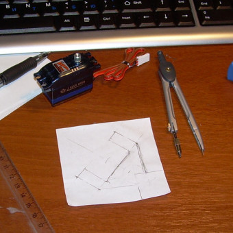
We measure the adapter board for the motor controllers and the motor mount and draw for some reason in the Compass:

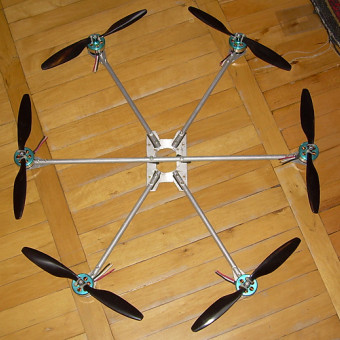
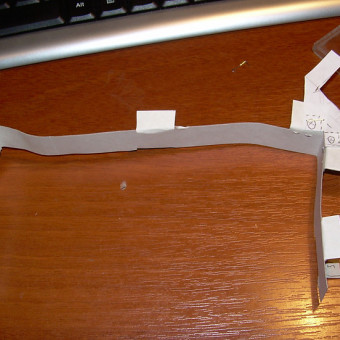
Despite the fact that the mounting of the motors to the carrying pipes is quite simple, we had to sweat a lot, cutting out the platform from the aluminum plate:

It is also difficult to drill holes in the pipes strictly perpendicular to the pipe. To do this, you need to get somewhere a special device, which I did not find, so it turned out crooked. From this point of view, it would be more appropriate to use aluminum profiles of square section, although it is said that a round pipe dampens vibration better.
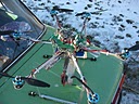
The central plate of my authorship, the pipes are mounted between two such plates and gaskets of micropores:
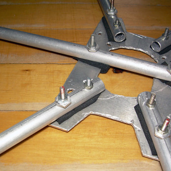
A piece of the frame assembly. Weight 700 g with motors, vibration damping is wonderful, so far so good.
A very important lesson I learned from the weeks of cutting and kilograms of chips: “on the knee” such things are not done, you need to look for professional equipment. Well, or I just have my hands out of my ass. In parallel with this thought, information came to me that there have long been offices that laser-cut everything from the metal that you draw, and is relatively inexpensive (~ $ 4.3 per meter cut in our latitudes). Being inspired, I estimated the “pattern” of the camera's suspension in order to cut along with other details:
Drawing in AutoCade was simply fabulously convenient and exciting, I don’t think there is a better CAD engineering than this one. However, I was disappointed: in the office the laser stopped taking duralumin thicker than 1.5 mm. And on sensations from feeling this dural, one and a half millimeters was clearly not enough. I had to do it myself again, and again with the handles:
When designing your own version of the frame, you need to immediately foresee the attachment points for all components, otherwise then it will come out sideways, you will have to sculpt details anywhere.
More on the camera suspension. I did not manage to make a normal suspension, it turned out to be a monstrous design with a rather big backlash. Servos do not have enough power to move this gimbal, so even unloaded, it leans in jerks. Must do with the gearbox. And in general, in my opinion, this is the most difficult part of the device, it must be carefully designed and manufactured using professional equipment.
More about the frame can be read on the website of Andrew and the forum there. It should be noted that there are many great ideas on this forum, they only need to be searched.
All the information is described in some detail here , I’d just add that it was quite convenient to buy wires of two colors, and solder the hh-hh-hh-h combinations in turn, and then solder one color to the white and black wires of the motor, and the red one is different. In this case, the motors turn in opposite directions, through one. However, do not rush to heat up the heat shrink tubing until you check to see if the motors are turning in the right direction. In order for the motor to spin in a different direction, it is enough to swap any two wires.
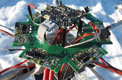
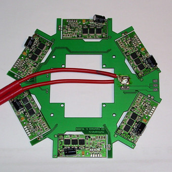
To begin with, we solder six controllers to the distribution board (however, this is not necessary, controllers can be located closer to the motors, but then it is necessary to provide fixings for them), to the corresponding contact pads of the 12AWG wire (with the battery connector observing polarity), and to the controller outputs wires 16AWG. Address areas are left intact.

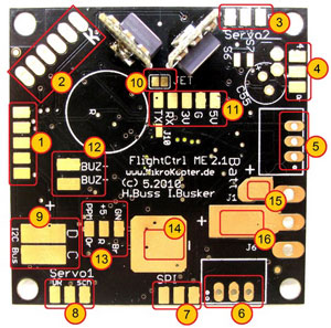 To the main board you need to solder the connectors for servos (3,4,8) and computer connections (1), power wires (already from the distribution board, 14 and 16), i2c bus (9) leading to the distribution board and the receiver (13 or 11). Full details here and here . And also, about the receiver . Together with the main board I immediately bought radio modems, it is very convenient. They need to be soldered and adjusted exactly according to this or this manual.
Multicopter, in fact, is almost ready. It remains to assemble the frame, distribution board, main board, attach the radio modem, battery and receiver. The setting of parameters is remarkably described on Andrei ’s site here and here , so I see no need to rewrite this manual again.


Feet had to do really quite anything, but it is not critical. As a result, a not very trustworthy construction came out, however, it showed itself quite well in trials.
After months of (un) fruitful work and soldering improperly soldered wires, the time has come "H". A relatively windless frosty morning is a wonderful day to kill nearly two thousand dollars.

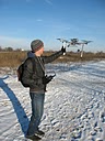
It is very difficult to control a flying machine from unaccustomed. Especially when it is crookedly assembled, and the corresponding coefficients are not configured in the autopilot. The tests had to be carried out with a tethered multi-rotor, or at least to enable height control, which I forgot to do. As a result, the device soared into the sky, and from there it was carried on to a passer-by who was gazing at the test. By this time I didn’t understand at all in which direction the onboard board was looking, and it was not possible to gently land the device. However, I was lucky again, and the damage turned out to be small: one carrier tube was broken, the legs of the multicopter were broken, and almost all the propellers were repulsed.

Now it is necessary to alter the frame a little, having provided a protective frame, legs, etc., and after that - a couple more tests, this time be careful. In addition, the issue with the suspension of the camera remains open.
I apologize for the somewhat confused and crumpled style of presentation, in the end it turned out that most of the information is described in some detail on other sites, and my own "achievements" relate more likely to correcting my own blunders, and do not deserve attention.
Thank you for flying with our airlines.
The Napoleonic plans described in the previous parts turned out to be practically impracticable by my far from even hands and the scanty forces of two or three people. Therefore, having been inspired by one of the efficient thoughts of the ReWork book, I decided to assemble the flying vehicle. As quickly as possible and with a minimum of effort this time.
')
But it was not there.
Details
Of the huge number of finished projects, I liked German most of all, especially considering that Andrey, the founder and inspirer of the site of a large Russian-speaking community of multicopter enthusiasts , stopped at it. What else will be required details, I approximately described in the previous parts. Putting it all together by adding specifics:
| Components | where to take | how much | how much 1 | for all |
|---|---|---|---|---|
| Motors | 700kV or 860kV | 7-8 2 | 12 $ -16 $ | 85 $ -130 $ |
| Motor controllers | V1.2 or V2.0 3 | 6 | 56 $ -76 $ | 336 $ -456 $ |
| Propellers | 10x4.5 or 12x4.5 | > 16 | 2.7 $ -3.7 $ | 40.5 $ -55.5 $ |
| Batteries | 5000mAh 3S1P | 2-4 | 28 $ | 56 $ -112 $ |
| Charger | IMAX B6 | one | 28 $ | 28 $ |
| Remote and receiver | simple 4 or more abruptly | one | 66 $ -190 $ | 66 $ -190 $ |
| Connectors | gold plated | a dozen | 4 $ -6 $ | 4 $ -6 $ |
| Wires | 12AWG and 16AWG | 2 m + 7m | $ 2.5; 1.4 $ | $ 15 |
| Main board | Flight-Ctrl V2.1 | one | 485 $ | 485 $ |
| Usb adapter | MK USB | one | $ 25.5 | $ 25.5 |
| Frame materials | in stores, in the markets | - | 20 $ -50 $ | 20 $ -50 $ |
| Servos | quite good and even better | 2-3 | 23 $ -47 $ | 46 $ -140 $ |
| Controller board | Hexa power distribution board * | one | $ 35 | $ 35 |
| Radio modems | Wi232 + Adapter board * | 2 | 67 $ | 134 $ |
| Videolink | 900MHZ 100mW + camera * | one | $ 47 | $ 47 |
2. Depending on how many motors are supposed in the device plus one or two spare ones.
3. Differ in power and additional buns. If I understood correctly, we don’t need additional buns of V2.0 controllers, and the power of V1.2 can be increased by replacing the firmware and mosfets.
4. You will need to buy or solder a PPM converter to it . There is another transmitter, but it is not available.
* - optional part.
Total: $ 1415 - $ 1905.
If you still have some money, you can purchase navigation modules: a magnetic sensor , a navigation card and GPS ($ 90 + $ 170 + $ 112). In fact, the upper price ceiling is practically unlimited. You can order a heavy-duty carbon fiber body, a three-kilogram motor for 20 horsepower and a multikopter rivet capable of lifting hundreds of kg into the air ... But something I dreamed about.
So, suppose the details arrived to us safely (oh, not at once it was! Well, at least without customs clearance). We proceed to the assembly. Further material will closely overlap with the site of Andrei, on which there is a huge pile of articles on individual parts and assembly in particular, so that to expand the horizons, you can glance there.
Camera frame and mount
I didn’t like the classic central plate with a round shape and square section profiles, so I stocked up with aluminum plates (thickness 1.5-2.5 mm, price $ 5 for 900 cm², yes, a little dirty), aluminum pipes (external diameter 10 mm, wall thickness 1 mm, price $ 4 for 2 m), paper and imagination.
We measure the adapter board for the motor controllers and the motor mount and draw for some reason in the Compass:
Despite the fact that the mounting of the motors to the carrying pipes is quite simple, we had to sweat a lot, cutting out the platform from the aluminum plate:
It is also difficult to drill holes in the pipes strictly perpendicular to the pipe. To do this, you need to get somewhere a special device, which I did not find, so it turned out crooked. From this point of view, it would be more appropriate to use aluminum profiles of square section, although it is said that a round pipe dampens vibration better.
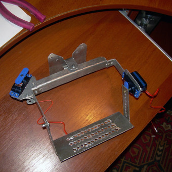
The central plate of my authorship, the pipes are mounted between two such plates and gaskets of micropores:
A piece of the frame assembly. Weight 700 g with motors, vibration damping is wonderful, so far so good.
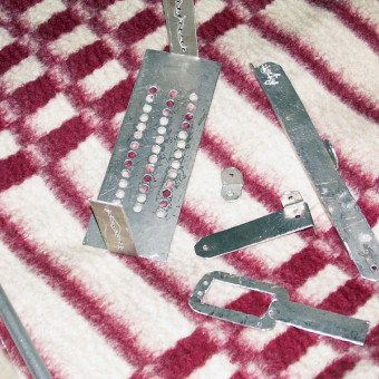
A very important lesson I learned from the weeks of cutting and kilograms of chips: “on the knee” such things are not done, you need to look for professional equipment. Well, or I just have my hands out of my ass. In parallel with this thought, information came to me that there have long been offices that laser-cut everything from the metal that you draw, and is relatively inexpensive (~ $ 4.3 per meter cut in our latitudes). Being inspired, I estimated the “pattern” of the camera's suspension in order to cut along with other details:
Drawing in AutoCade was simply fabulously convenient and exciting, I don’t think there is a better CAD engineering than this one. However, I was disappointed: in the office the laser stopped taking duralumin thicker than 1.5 mm. And on sensations from feeling this dural, one and a half millimeters was clearly not enough. I had to do it myself again, and again with the handles:
When designing your own version of the frame, you need to immediately foresee the attachment points for all components, otherwise then it will come out sideways, you will have to sculpt details anywhere.
- Fastening support tubes . It is possible to leave one pipe whole (as in my photos above), the rest to be fixed to the plates in two places with bolts, at a distance of 2 cm one from the other.
- Mount the main board . As it turned out, it can not be set as horrible, but only in several ways.
- Mount the camera mount . Wonderful vibration protection by hanging the camera mounting plate on thick garden hose sections .
- Mount the battery . I was lucky, I managed to attach the battery on the suspension of the camera. In the comments to the previous articles, they suggested making steadycam as a suspension, which has a battery instead of a load.
- Fastening modem and receiver . I forgot about them, so I had to tape the tape straight to the carrying pipes. Not very aesthetically pleasing, but quite reliable, since these boards weigh almost nothing.
- Mount "legs" . About him, too, had to be remembered, because again to mount the legs to the supporting pipes is a bad idea.
More on the camera suspension. I did not manage to make a normal suspension, it turned out to be a monstrous design with a rather big backlash. Servos do not have enough power to move this gimbal, so even unloaded, it leans in jerks. Must do with the gearbox. And in general, in my opinion, this is the most difficult part of the device, it must be carefully designed and manufactured using professional equipment.
More about the frame can be read on the website of Andrew and the forum there. It should be noted that there are many great ideas on this forum, they only need to be searched.
Motor controllers
All the information is described in some detail here , I’d just add that it was quite convenient to buy wires of two colors, and solder the hh-hh-hh-h combinations in turn, and then solder one color to the white and black wires of the motor, and the red one is different. In this case, the motors turn in opposite directions, through one. However, do not rush to heat up the heat shrink tubing until you check to see if the motors are turning in the right direction. In order for the motor to spin in a different direction, it is enough to swap any two wires.
To begin with, we solder six controllers to the distribution board (however, this is not necessary, controllers can be located closer to the motors, but then it is necessary to provide fixings for them), to the corresponding contact pads of the 12AWG wire (with the battery connector observing polarity), and to the controller outputs wires 16AWG. Address areas are left intact.
Main board
To the main board you need to solder the connectors for servos (3,4,8) and computer connections (1), power wires (already from the distribution board, 14 and 16), i2c bus (9) leading to the distribution board and the receiver (13 or 11). Full details here and here . And also, about the receiver . Together with the main board I immediately bought radio modems, it is very convenient. They need to be soldered and adjusted exactly according to this or this manual.Build and configure
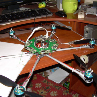
Multicopter, in fact, is almost ready. It remains to assemble the frame, distribution board, main board, attach the radio modem, battery and receiver. The setting of parameters is remarkably described on Andrei ’s site here and here , so I see no need to rewrite this manual again.
Feet had to do really quite anything, but it is not critical. As a result, a not very trustworthy construction came out, however, it showed itself quite well in trials.
Tests
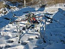
After months of (un) fruitful work and soldering improperly soldered wires, the time has come "H". A relatively windless frosty morning is a wonderful day to kill nearly two thousand dollars.
It is very difficult to control a flying machine from unaccustomed. Especially when it is crookedly assembled, and the corresponding coefficients are not configured in the autopilot. The tests had to be carried out with a tethered multi-rotor, or at least to enable height control, which I forgot to do. As a result, the device soared into the sky, and from there it was carried on to a passer-by who was gazing at the test. By this time I didn’t understand at all in which direction the onboard board was looking, and it was not possible to gently land the device. However, I was lucky again, and the damage turned out to be small: one carrier tube was broken, the legs of the multicopter were broken, and almost all the propellers were repulsed.
Now it is necessary to alter the frame a little, having provided a protective frame, legs, etc., and after that - a couple more tests, this time be careful. In addition, the issue with the suspension of the camera remains open.
I apologize for the somewhat confused and crumpled style of presentation, in the end it turned out that most of the information is described in some detail on other sites, and my own "achievements" relate more likely to correcting my own blunders, and do not deserve attention.
Thank you for flying with our airlines.
Source: https://habr.com/ru/post/114327/
All Articles