Policy-based Routing (PBR), as the main purpose (Part 2)
Preface.
As they said in the comments to the first article, that they might not reach the second article, as they looked into the water. She lay unfinished for a very long time. Now I drove a little bit, but I had to give up many details and wishes that were expressed in the comments to the first part. But I think all the same interest will cause this continuation of the article, although it was expressed that PBR is a banal and hackneyed topic. In other matters, I agree, but to write the next article, you still need to complete what you started earlier .
Who is interested in the continuation of the article welcome under the cat
Acquaintance with the scheme.
')
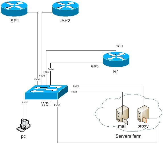
For further acquaintance with PBR, I sketched a virtual office diagram. It consists of 3 routers, a switch, 2 servers and a symbolic client, which represents user PCs in a single person:
1. The router of our office (R1).
2. The primary provider's router (ISP1).
3. Backup Provider Router (ISP2).
4. Mail server (mail)
5. Proxy server (proxy)
6. Switch (ws1)
7. Client (PC)
Also, I did not display a remote office on the diagram, but in the article it will be implied.
And so easy description of the scheme. We have a network of users, 192.168.0.0/27, they need services such as internal mail, the Internet, and others that are not fixed in our scheme. The servers will live with us on the network 192.168.0.32/29 (2 servers, an internal mail server, and a proxy server are shown in the diagram). Well, the external network (I'll take the gray network, meaning white under them). Total we will receive the following address plan.
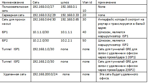
The initial data, we have now turned to the configuration of the equipment, at first I will set up the virtual office equipment, as they say "that would work" (I will not give complete configurations like the PBR article). When transferring the original data to the configuration, we get, like this:
R1#sh run | b int
interface Tunnel1
description ### tunnel over ISP1 ###
ip address 192.168.1.1 255.255.255.252
tunnel source 10.1.1.2
tunnel destination 10.0.0.2
!
interface Tunnel2
description ### tunnel over ISP2 ###
ip address 192.168.2.1 255.255.255.252
tunnel source 10.2.2.2
tunnel destination 10.0.0.2
!
interface GigabitEthernet0/0
no ip address
duplex auto
speed auto
!
interface GigabitEthernet0/0.10
description ### client network ###
encapsulation dot1Q 10
ip address 192.168.0.1 255.255.255.224
!
interface GigabitEthernet0/0.20
description ### servers network ###
encapsulation dot1Q 20
ip address 192.168.0.33 255.255.255.224
!
interface GigabitEthernet0/0.30
description ### proxy out int ####
encapsulation dot1Q 30
ip address 192.168.0.65 255.255.255.252
!
interface GigabitEthernet0/1
no ip address
duplex auto
speed auto
!
interface GigabitEthernet0/1.40
description ### ISP1 p-to-p ###
encapsulation dot1Q 40
ip address 10.1.1.2 255.255.255.252
!
interface GigabitEthernet0/1.50
description ### ISP2 p-to-p ###
encapsulation dot1Q 50
ip address 10.2.2.2 255.255.255.252
Switch configuration ws1, I will not bring. Let's take a word that all the ports in their vlans, the ports in the mode trunk, allow only the necessary authorities to pass. Similarly, we can say about the server, they are configured and correctly work out their task.
The situation when you just need a flexible routing.
So, we have a virtual office, and we want to control users, count traffic, etc. for this we have a proxy server (hereinafter simply proxy), therefore we need to wrap traffic from the user network to the proxy. There is a problem, we proceed to the solution.
First you need to choose a network for which we will “draw” a routing map.
This can be done in 2 ways through the ACL, or mark (apply) the traffic that passes through the logical interface, we send to porxy.
do the card either like this:
access-list 101 permit ip 192.168.0.0 0.0.0.31 any
!
route-map client permit 5
match ip address 101
set ip next-hop 192.168.0.35
either so:
route-map clientif permit 5
match interface GigabitEthernet0/0.10
set ip next-hop 192.168.0.35
there is another way, without using the parameter, match, the card is simply hung with the set parameter on the interface, but I’m not sure about 100 percent performance, and it is fraught with consequences, applying it (theoretically) to anyone interested can try to see.
What we get in the end. All client traffic will go to our proxy, and then the proxy will have to think, consulting with its routing table, where to send the traffic. With such a picture, we have a little nuance. Clients (MUA), access the mail server (MTA), through an extra hop (proxy), and this is an already possible extra problem of providing services, in particular a sweat service. After all, proxy administrators can not only, for example, overload the server, but also disable operational settings, and the banal iron failure on the server, and you, as luck would have it, is not in place and there is no access to the router. In general, it is not entirely correct, here it is better to bypass this extra hop. This is also done in several ways:
1. The way it is - to register instead of ip next-hop , ip default next-hop . Thus, the map will not work for mail, since we have it in the global routing table on the network that has a direct connection .
2. A way to rewrite our access sheet
access-list 101 deny ip 192.168.0.0 0.0.0.31 host 192.168.0.34
access-list 101 permit ip 192.168.0.0 0.0.0.31 any
Naturally, here you can modify, for example, so that our clients would go to the servers directly without the participation of a proxy, then instead of:
access-list 101 deny ip 192.168.0.0 0.0.0.31 host 192.168.0.34write
access-list 101 deny ip 192.168.0.0 0.0.0.31 192.168.0.34 0.0.0.31Or draw a map with ports. Those. for example, you want to control access via RDP, to the proxy, but clients go through mail ports on a straight line, then we draw sheets like this:
access-list 101 deny tcp 192.168.0.0 0.0.0.31 host 192.168.0.34 eq smtp
access-list 101 permit ip 192.168.0.0 0.0.0.31 any
about ip locacl policy.
And so we have 2 providers. To begin, let's set up communication between our router and providers. First of all, we will draw, so that the interfaces on the router respond through its gateway, this is to avoid routing loops, i.e. from where the packet came to our router there it will go. The picture we are trying to avoid looks like this: we have one of the gateways to the Internet 10.1.1.1, it is registered on the router as the default route. When trying to get from the Internet to the router at 10.2.2.2, the packets will reach it, but in response it will be sent through the gateway 10.1.1.1 since, it is our default route. And there and the channel can "lie" and just the equipment provider will not know about the network 10.2.2.0/30, or large delays. We do the following steps:
but. We write 2 sheets for 2 independent networks of the provider.
access-list 105 permit ip 10.1.1.0 0.0.0.3 any
access-list 106 permit ip 10.2.2.0 0.0.0.3 any
b. draw a route map
route-map r1 permit 10
match ip address 105
set ip next-hop 10.1.1.1

route-map r1 permit 15
match ip address 106
set ip next-hop 10.2.2.1
at. We apply our map, on the local policy of the router.
ip local policy route-map r1here it is worth noting that when applying a card to ip local policy there will be a redirection of traffic that is generated on the router itself, and traffic that does not fall under the processing of the route map will act according to the global policy of the router. We also have other networks on the router that communicate only between networks directly connected to the router, so that the rest of the networks also have a default gateway just add this kind of string
route-map r1 permit 30
set ip next-hop 192.168.1.2
it is assumed that this hop is located at the remote office, with which you need to exchange traffic with the remaining networks. Since we have 2 tunnels, through 2 providers, then it’s fair to make a reservation in case the main tunnel falls. This is done using SLA.
It was described in sufficient volume and not only on the habr, I omit this moment.
a little about nat & pbr
At the moment we will assume that our internal routing is organized, at least our users go through a proxy, they access the Internet to the server network bypassing the proxy.
But if we leave in such a state, the users, having arrived at work, will want to read their favorite resources on the network, check their email, and they don’t have the Internet, then, having made sure that besides their personal resources, they also don’t work, a scream will immediately rise.
To avoid this, we must finish the job. We take, we broadcast the proxy address to the white addresses of providers.
ip nat source route-map proxy1 interface GigabitEthernet0/1.40
ip nat source route-map proxy2 interface GigabitEthernet0/1.50
And then “babats” and the translation does not work, nat and locacl policy will not work, because for the translation of addresses, a route in the global routing table is necessary. Those. the need to set default routes for 2 providers, has not been canceled. Well and tracking here it is fastened.
Small details and subtleties of the mechanism.
In the previous part, in the comments, I skipped questions and wishes to describe the load on the processor of the router. I will say that he eats little and will not notice the visible load. For example, on the Catalyst 4948e, when routing through PBR in the region of 3 gigs, the load is practically not observed. And since the topic has come to download. I’ll say PBR from version 12.0 supports cef technology (cisco express forvarding) it is enabled by default, in order to turn off cef for PBR, just give the ip route-cache policy command on the interface that holds the card (of course on the physical and not on the subinterface.) , which includes fast-switching which stores the routes in the cache and also does not heavily load the processor, but with fast-switching does not support the set ip default next-hop command.
By this, I think it is worth not experimenting, and use cef .
Well, without a description and details, I will say that it is possible to check whether pbr is working or not by such commands sh route-map all or the name of the map itself, the most important data is shown in the form:
Policy routing matches: 76013668 packets, 3726692270 bytes
debug ip policy here we do not forget that you can put a router by downloading cpu
keywords policy routed this means that the package left according to the drawn card,
and policy rejected - normal forwarding the opposite situation, when the packet went according to the global table.
Posted by Mario
Source: https://habr.com/ru/post/114197/
All Articles