Building a multikopter, part two
Part 1 | Part 2 | Part 3 | Part 4
So, we are full of enthusiasm and are ready to spend money-time-power on this great idea.

')
In order to determine the angles of inclination / rotation of the multicopter in three axes (and this is a vital task for the stabilization of the device in the air), you can use different sensors: optical (video processing coming from the camera), pyrometric (slightly trimmed optical version, according to signals from four of these sensors you can track the horizon line), magnetic and inertial. The ideal option would be to use all together, but we have extremely poor computational capabilities of the microcontroller, so we’ll dwell on the gyroscopes traditional for air navigation.
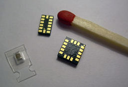
Modern advances in microelectronics allowed us to assemble a mechanical (more precisely, MEMS ) gyroscope in a 5x5 mm package. ST and Analog Devices provide a whole line of microscopic gyroscopes and accelerometers for every taste and sensitivity.
Theoretically, only gyroscopes could be used to determine angles, but there are a number of problems. Gyroscopes show the angular velocity of rotation (some voltage level proportional to this speed), but they have such a phenomenon as drift: shifting the zero value to a random direction (in my hands this manifested itself as residual dizziness of the sensor after I stopped rotate). The rapid accumulation of errors will not allow to do without other sensors.
There are accelerometers, which similarly provide information about the acceleration applied to them. An important point: accelerometers show the difference between the actually applied acceleration and the usual g, and therefore, by simple calculations, from the signals from the three accelerometers directed along different axes, you can get the angles of rotation of the system of calculation of our apparatus relative to the system of land in the original it is a frame of reference). But as soon as our device receives any acceleration, the angles obtained will be inaccurate (and if the acceleration is large, it is completely incorrect).
In order to relate the values obtained from both types of sensors, a Kalman filter is traditionally used, which is long understood, but it gives an excellent result, and there are many examples of its implementations on the Internet.
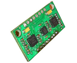
In principle, it was possible to immediately buy one of the ready-made inertial navigation modules with the software already written, but this is not sports , right? Therefore, we purchased a pair of digital ( and why do we need analog? I2C taxis! ) MEMS-parts and began to read their specifications in order to solder a fee for them.
However, it quickly became clear that it was very boring and time-consuming to draw a board for an unknown device (even footprints — soldering templates — you need to draw from scratch). It is better to try to implement a ready-made sensor module , there is already a layout for it, just take it and print it ( Buy it? Nooo, why pay $ 70 and wait for it to be brought! ). At the same time we will master the method of laser iron , it will come in handy.

We print templates (more than once, because we constantly forget to mirror)

Ironing a dozen times until we get clear tracks without gaps.

Grass and scour toner. We are convinced that something is not cured, we repeat the above steps.
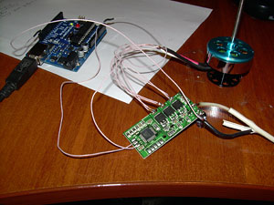
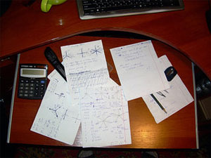
At the same time, we straighten the lazy convolutions by trigonometry and “invent” the control algorithm. We connect (hooh, this time even bought) engine controllers to arduine. The power supply from the computer could not power one unloaded motor at medium speed. Strength.
It should be noted, this was done not a day, and not a week. While for parts you will go to the market four times (you will always forget something, or not), while the accelerometer that was not available is brought from America ...
And then suddenly came the realization that the metallization of the holes in the board of the house would not work, because the holes are right under the belly of the gyroscopes and accelerometers in the QFN package, which is directly adjacent to the board. To put it mildly, we felt sad. I had to order a fee for production, which cost $ 17 for two dozen pieces (minimum order). Another obstacle was waiting for us when trying to solder the parts in these same buildings without legs, since we did not have a soldering station. However, for a nominal fee, those who found it helped us with this. I even keep silent about the fact that I couldn’t make this scheme work for a long time, because you need to read the specification more carefully.

It seems true?
So, we finally have a ready board with accelerometers and gyroscopes, you can start writing software. And even the thought that electronics do from habit is beginning to creep into my head - a rather ungrateful occupation. But just starting.
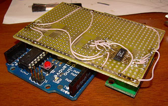
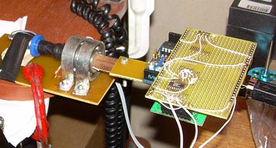
For debugging, we collect some semblance of an arduino-shield with a simple ADC.
You can even attach it all to the test site, rotating the potentiometer, assuming that the potentiometer will show us an “honest” angle. For reference, it is not.
Having superficial programming skills in everything that is compiled, interpreted, or converted to bytecode, we sketched something like a program to get values from the sensors, store them in a CSV file for Excel processing, and also display the 3D model and display graphs in real time.
First of all we get the values of the sensors lying motionless:
When you try to move the sensors, the noise increases. It is terrible to think what noise will be from 6 engines.
We turn the board:
Naturally, the obtained values of the angles of rotation of each sensor differ. However, the second figure clearly shows the deviation of the angle values according to the accelerometer version and according to the potentiometer, and they should be more or less the same.
It turns out that the resistance of the potentiometer varies nonlinearly depending on the angle of rotation. I would even say chaotically.
All tired of graphics. We throw out the potentiometer, rewrite the implementation of the Kalman filter from C to C #, we get a more or less adequate response to turns.
(here both windows show the same thing, but the visualization is very close to the actual position of the sensors in the hand). Everything is working.
UPD
SovGVD writes:
I think it is not worth dividing into small notes, 20-30 will still be at such rates + it would be worth mentioning the Wii Motion Plus (an example of what I ordered with dx) and the Wii Nunchack are a gyroscope and accelerometer, respectively, on which a lot of people fly: multiwii .com and at times, everything is going to be easier ... accuracy is not perfect, of course, but the price is cheap, you just have to get the boards and
To be continued.
It should be noted, the topic with accelerometers (and other navigation sensors) will now be gaining popularity, both in the context of the AR , and for UAVs. But what to say, even in segways the same inertial system is used. Anyone who is friends with Matan can develop more efficient and reliable algorithms.
And you can start with a couple of dihalt records a.
So, we are full of enthusiasm and are ready to spend money-time-power on this great idea.
')
Let's start with the sensors
In order to determine the angles of inclination / rotation of the multicopter in three axes (and this is a vital task for the stabilization of the device in the air), you can use different sensors: optical (video processing coming from the camera), pyrometric (slightly trimmed optical version, according to signals from four of these sensors you can track the horizon line), magnetic and inertial. The ideal option would be to use all together, but we have extremely poor computational capabilities of the microcontroller, so we’ll dwell on the gyroscopes traditional for air navigation.
Modern advances in microelectronics allowed us to assemble a mechanical (more precisely, MEMS ) gyroscope in a 5x5 mm package. ST and Analog Devices provide a whole line of microscopic gyroscopes and accelerometers for every taste and sensitivity.
Theoretically, only gyroscopes could be used to determine angles, but there are a number of problems. Gyroscopes show the angular velocity of rotation (some voltage level proportional to this speed), but they have such a phenomenon as drift: shifting the zero value to a random direction (in my hands this manifested itself as residual dizziness of the sensor after I stopped rotate). The rapid accumulation of errors will not allow to do without other sensors.
There are accelerometers, which similarly provide information about the acceleration applied to them. An important point: accelerometers show the difference between the actually applied acceleration and the usual g, and therefore, by simple calculations, from the signals from the three accelerometers directed along different axes, you can get the angles of rotation of the system of calculation of our apparatus relative to the system of land in the original it is a frame of reference). But as soon as our device receives any acceleration, the angles obtained will be inaccurate (and if the acceleration is large, it is completely incorrect).
In order to relate the values obtained from both types of sensors, a Kalman filter is traditionally used, which is long understood, but it gives an excellent result, and there are many examples of its implementations on the Internet.
Production of a payment for sensors
In principle, it was possible to immediately buy one of the ready-made inertial navigation modules with the software already written, but this is not sports , right? Therefore, we purchased a pair of digital ( and why do we need analog? I2C taxis! ) MEMS-parts and began to read their specifications in order to solder a fee for them.
However, it quickly became clear that it was very boring and time-consuming to draw a board for an unknown device (even footprints — soldering templates — you need to draw from scratch). It is better to try to implement a ready-made sensor module , there is already a layout for it, just take it and print it ( Buy it? Nooo, why pay $ 70 and wait for it to be brought! ). At the same time we will master the method of laser iron , it will come in handy.
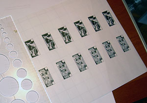
We print templates (more than once, because we constantly forget to mirror)
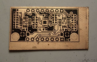
Ironing a dozen times until we get clear tracks without gaps.
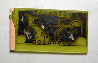
Grass and scour toner. We are convinced that something is not cured, we repeat the above steps.
At the same time, we straighten the lazy convolutions by trigonometry and “invent” the control algorithm. We connect (hooh, this time even bought) engine controllers to arduine. The power supply from the computer could not power one unloaded motor at medium speed. Strength.
It should be noted, this was done not a day, and not a week. While for parts you will go to the market four times (you will always forget something, or not), while the accelerometer that was not available is brought from America ...
And then suddenly came the realization that the metallization of the holes in the board of the house would not work, because the holes are right under the belly of the gyroscopes and accelerometers in the QFN package, which is directly adjacent to the board. To put it mildly, we felt sad. I had to order a fee for production, which cost $ 17 for two dozen pieces (minimum order). Another obstacle was waiting for us when trying to solder the parts in these same buildings without legs, since we did not have a soldering station. However, for a nominal fee, those who found it helped us with this. I even keep silent about the fact that I couldn’t make this scheme work for a long time, because you need to read the specification more carefully.
It seems true?
So, we finally have a ready board with accelerometers and gyroscopes, you can start writing software. And even the thought that electronics do from habit is beginning to creep into my head - a rather ungrateful occupation. But just starting.
Get the data
For debugging, we collect some semblance of an arduino-shield with a simple ADC.
You can even attach it all to the test site, rotating the potentiometer, assuming that the potentiometer will show us an “honest” angle. For reference, it is not.
Having superficial programming skills in everything that is compiled, interpreted, or converted to bytecode, we sketched something like a program to get values from the sensors, store them in a CSV file for Excel processing, and also display the 3D model and display graphs in real time.
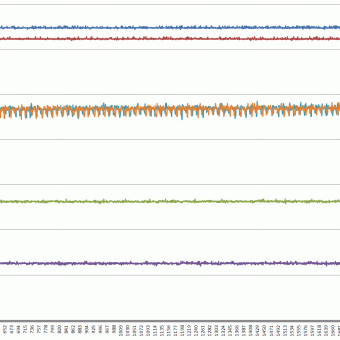
First of all we get the values of the sensors lying motionless:
When you try to move the sensors, the noise increases. It is terrible to think what noise will be from 6 engines.
We turn the board:
Naturally, the obtained values of the angles of rotation of each sensor differ. However, the second figure clearly shows the deviation of the angle values according to the accelerometer version and according to the potentiometer, and they should be more or less the same.
It turns out that the resistance of the potentiometer varies nonlinearly depending on the angle of rotation. I would even say chaotically.
All tired of graphics. We throw out the potentiometer, rewrite the implementation of the Kalman filter from C to C #, we get a more or less adequate response to turns.
(here both windows show the same thing, but the visualization is very close to the actual position of the sensors in the hand). Everything is working.
UPD
SovGVD writes:
I think it is not worth dividing into small notes, 20-30 will still be at such rates + it would be worth mentioning the Wii Motion Plus (an example of what I ordered with dx) and the Wii Nunchack are a gyroscope and accelerometer, respectively, on which a lot of people fly: multiwii .com and at times, everything is going to be easier ... accuracy is not perfect, of course, but the price is cheap, you just have to get the boards and
To be continued.
It should be noted, the topic with accelerometers (and other navigation sensors) will now be gaining popularity, both in the context of the AR , and for UAVs. But what to say, even in segways the same inertial system is used. Anyone who is friends with Matan can develop more efficient and reliable algorithms.
And you can start with a couple of dihalt records a.
Source: https://habr.com/ru/post/113735/
All Articles