Building a multicopter, part one
Part 1 | Part 2 | Part 3 | Part 4
Recently, the multi-rotor scheme of the aircraft, the so-called multicopters, is gaining popularity among model airplanes and their sympathizers. Since there is still no corresponding Wikipedia article, and only references to this funny mechanism flashed on Habré, I decided to share the experience of building my own apparatus.
')
Looking ahead, I’ll say that it’s not overly beautiful, but for those who don’t care about the result, I’m inviting you to the process, under the cut, where it smells like rosin and aluminum filings are scattered.
A few years ago, the idea of shooting a city from a bird's eye knocked on my head. Having run through available options like raising a camera on a kite , on a balloon and even pigeons , I quickly and naturally came to the idea of a radio-controlled helicopter, and possibly a new and unexplored mechanism — a multicopter.
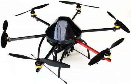
Most often the multicopter is a metal or carbon-plastic frame with a twin number of motors (quad and hexacopters are most popular, with 4 and 6 rotors, respectively). In the center there is a control board and a battery, the rest of the parts are mounted, wherever they please.
Electric three-phase brushless motors (standard for model airplanes) at 7000-25000 revolutions per minute develop cravings sufficient to hold all the equipment needed for surveys in the air. Depending on the number and power of the motors, this thrust can be from hundreds of grams to tens of kilograms .
In most cases, an even number of rotors is used to evenly compensate for the rotational moment: half of the propellers spin in one direction, half in the opposite direction (for the same purpose, a tail rotor is provided for a classic helicopter), although there are trictors .
Thus, for tilting the device to the right and left and back and forth (roll and pitch), it is enough to reduce the speed of rotation of the motors on the one hand, and increase it on the other, and if you increase the speed of the motors “through one”, the rotational moment of some will not be compensated by others , and the device will rotate around the vertical axis left-right (yaw). In tricopter one of the motors can change the axis of rotation, directing its thrust a little to the side, but for this you need to overcome the gyroscopic effect, so I consider tricopter ineffective.
The multi-rotor has several advantages over the classic helicopter model:
So, we are set on trying to assemble a multicopter for photographic purposes. We are not satisfied with ready-made solutions (about them later), we want to create something of our own, big, beautiful, with appropriate card games and girls of easy virtue. For the cause!
We need to get a device that
It doesn’t look like it at all, since it’s not at all clear what we have, but after some googling the picture becomes clearer. The range of brushless motors pleases the eye, but sometimes saddens the wallet. Let us use the experience of our foreign colleagues (we will also return to them later), and determine that the most convenient for us are 700kv and 860kv motors (kv is revolutions per minute per volt).
Still believing that we’ll manage with a little blood, we’ll stop at a cheaper model, which gives 700 revolutions per volt, and with peak consumption of 15A at 10x4.7 cm blades we expect to get almost a kilogram of thrust from each motor. Thus, the maximum total thrust is assumed to be around 4.8 kg, the current consumption is 90A. Immediately make a reservation, I didn’t have any business with aviation before, so I base myself on fragments of phrases read in the vast forums.
Also comes across a wonderful 5000 mAh battery , on which we can fly as much as 3.3 minutes. This does not suit us very much, so we simply assume that the consumption will be slightly less than 90A :) One more reservation: the calculations were carried out with a “finger to the sky”, because nothing could be said with confidence until you touch everything with your hands and a tester.
On the rest of the points we will dwell.
We draw our thoughts on what our complex should consist of:
Motor controllers (they are also speed controllers) is a standard scheme for model airplanes that supplies engines with prepared 3-phase power supply with a phase shift depending on the PWM signal that sets the desired rotor speed. In the future, we will again use the experience of our foreign colleagues who modified the controller's firmware (and it was everybody's favorite ATmega) of one of the regulators so as to set the speed not with a PWM signal, but with a byte written to a specific address on the I2C bus. This method of control allows us to connect all the speed controllers and the control microcontroller with just three wires.
Gyrocube - I so called the set of three gyroscopes and three accelerometers necessary for the control board to track the position of the device in space.
Camera suspension is another important detail for shooting. In flight, the multicopter is tilted to the sides, so the camera needs to be tilted in the opposite direction, so that the camera is more or less in the same plane relative to the object to be removed, and the frame is not wobbly. Suspension designs exist in large numbers , they are all controlled by servos (it would be safer to hang a real gyroscope, but this is an impermissible waste of precious lifting power).
The main board (let's call it autopilot) is the most difficult part of the device. Using data obtained from gyroscopes and accelerometers, the microcontroller calculates the angle at which the multicopter is rotated around each of the axes in order to recalculate the required rotational speed of each propeller and align the device to its original position.
Remote - according to our plan, this is a laptop, which sends signals to the main board via a radio modem and in the same way receives data on the state of the device.
At this point, it seemed to us that we would cope with all that huge amount of work: software and hard, communication protocols and interaction schemes were to be developed, almost everything from scratch. It was a mistake, of which we made a lot, and we will allow it again and again, but we have gained experience, which may be useful to any of you. Well, or at least it will be just interesting to read :) spoiler
Thanks to everyone who helped this post appear;) To be continued .
Recently, the multi-rotor scheme of the aircraft, the so-called multicopters, is gaining popularity among model airplanes and their sympathizers. Since there is still no corresponding Wikipedia article, and only references to this funny mechanism flashed on Habré, I decided to share the experience of building my own apparatus.
')
Looking ahead, I’ll say that it’s not overly beautiful, but for those who don’t care about the result, I’m inviting you to the process, under the cut, where it smells like rosin and aluminum filings are scattered.
A few years ago, the idea of shooting a city from a bird's eye knocked on my head. Having run through available options like raising a camera on a kite , on a balloon and even pigeons , I quickly and naturally came to the idea of a radio-controlled helicopter, and possibly a new and unexplored mechanism — a multicopter.
A few words about the design
Most often the multicopter is a metal or carbon-plastic frame with a twin number of motors (quad and hexacopters are most popular, with 4 and 6 rotors, respectively). In the center there is a control board and a battery, the rest of the parts are mounted, wherever they please.
Electric three-phase brushless motors (standard for model airplanes) at 7000-25000 revolutions per minute develop cravings sufficient to hold all the equipment needed for surveys in the air. Depending on the number and power of the motors, this thrust can be from hundreds of grams to tens of kilograms .
In most cases, an even number of rotors is used to evenly compensate for the rotational moment: half of the propellers spin in one direction, half in the opposite direction (for the same purpose, a tail rotor is provided for a classic helicopter), although there are trictors .
Thus, for tilting the device to the right and left and back and forth (roll and pitch), it is enough to reduce the speed of rotation of the motors on the one hand, and increase it on the other, and if you increase the speed of the motors “through one”, the rotational moment of some will not be compensated by others , and the device will rotate around the vertical axis left-right (yaw). In tricopter one of the motors can change the axis of rotation, directing its thrust a little to the side, but for this you need to overcome the gyroscopic effect, so I consider tricopter ineffective.
The multi-rotor has several advantages over the classic helicopter model:
- Starting price. A helicopter with similar lift is twice as expensive.
- Simplicity of design. The frame is made of
shit and sticks ofscrap materials, strength is of secondary importance (some parts of a traditional helicopter must withstand enormous loads in order to allow sharp maneuvers). - Maintenance price. A helicopter with the necessary lift (hereinafter I mean that we want to end up with an aircraft capable of lifting, for example, an average SLR weighing 1.5–2 kg) can only have an internal combustion engine, huge blades and other delights of large models , with all the corresponding costs for gasoline + oil, broken blades and so on.
- Exploitation. This could include a much greater vibration and noise of a single-combustion engine than six electric engines; high multicopter maneuverability, easy control using autopilot.
So, we are set on trying to assemble a multicopter for photographic purposes. We are not satisfied with ready-made solutions (about them later), we want to create something of our own, big, beautiful, with appropriate card games and girls of easy virtue. For the cause!
Let's start with the draft outline.
We need to get a device that
- will stabilize itself in the air (not manual control),
- with a maximum carrying capacity (but which one? Surely we are limited either in the budget or in technical capabilities),
- maximum flight time (again, depends on payload),
- maximum communication range
It doesn’t look like it at all, since it’s not at all clear what we have, but after some googling the picture becomes clearer. The range of brushless motors pleases the eye, but sometimes saddens the wallet. Let us use the experience of our foreign colleagues (we will also return to them later), and determine that the most convenient for us are 700kv and 860kv motors (kv is revolutions per minute per volt).
Still believing that we’ll manage with a little blood, we’ll stop at a cheaper model, which gives 700 revolutions per volt, and with peak consumption of 15A at 10x4.7 cm blades we expect to get almost a kilogram of thrust from each motor. Thus, the maximum total thrust is assumed to be around 4.8 kg, the current consumption is 90A. Immediately make a reservation, I didn’t have any business with aviation before, so I base myself on fragments of phrases read in the vast forums.
Also comes across a wonderful 5000 mAh battery , on which we can fly as much as 3.3 minutes. This does not suit us very much, so we simply assume that the consumption will be slightly less than 90A :) One more reservation: the calculations were carried out with a “finger to the sky”, because nothing could be said with confidence until you touch everything with your hands and a tester.
On the rest of the points we will dwell.
Device diagram
We draw our thoughts on what our complex should consist of:
Motor controllers (they are also speed controllers) is a standard scheme for model airplanes that supplies engines with prepared 3-phase power supply with a phase shift depending on the PWM signal that sets the desired rotor speed. In the future, we will again use the experience of our foreign colleagues who modified the controller's firmware (and it was everybody's favorite ATmega) of one of the regulators so as to set the speed not with a PWM signal, but with a byte written to a specific address on the I2C bus. This method of control allows us to connect all the speed controllers and the control microcontroller with just three wires.
Gyrocube - I so called the set of three gyroscopes and three accelerometers necessary for the control board to track the position of the device in space.
Camera suspension is another important detail for shooting. In flight, the multicopter is tilted to the sides, so the camera needs to be tilted in the opposite direction, so that the camera is more or less in the same plane relative to the object to be removed, and the frame is not wobbly. Suspension designs exist in large numbers , they are all controlled by servos (it would be safer to hang a real gyroscope, but this is an impermissible waste of precious lifting power).
The main board (let's call it autopilot) is the most difficult part of the device. Using data obtained from gyroscopes and accelerometers, the microcontroller calculates the angle at which the multicopter is rotated around each of the axes in order to recalculate the required rotational speed of each propeller and align the device to its original position.
Remote - according to our plan, this is a laptop, which sends signals to the main board via a radio modem and in the same way receives data on the state of the device.
At this point, it seemed to us that we would cope with all that huge amount of work: software and hard, communication protocols and interaction schemes were to be developed, almost everything from scratch. It was a mistake, of which we made a lot, and we will allow it again and again, but we have gained experience, which may be useful to any of you. Well, or at least it will be just interesting to read :) spoiler
Thanks to everyone who helped this post appear;) To be continued .
Source: https://habr.com/ru/post/113680/
All Articles