Interactive map of the Arduino or in the footsteps of the "Admin Traffic Light"
For a system administrator working for an Internet provider, very often there is the task of monitoring a large number of active equipment. Of course, nagios, cacti, zabbix and similar monitoring tools can be used for these purposes. But they all have one major drawback - you must use the browser as a means of displaying the status of monitored network nodes.
Acquainted with the "admin traffic light" the idea of creating an interactive map of the city, with LEDs located on it: red - the node is unavailable, green - available. But if you use the described method of ignition of LEDs, you will need 2 xn, where n is the number of controlled nodes. Thus, to control 10 nodes, 20 pins will be needed. It is clear that this method for solving the problem, in the case of controlling more than 5 nodes, is not suitable.
So, how can you reduce the number of outputs used? From the go to the head comes the use of the decoder. The method is good, but you need to invent your cipher, in which you need to take into account all possible combinations of the work of controlled nodes. The method is good, but not very scalable.
More successful is the method of converting a serial signal into a parallel one. That is, a serial signal goes from the arduino board, and the LED control is already implemented in the additional circuit. Go this way and go.
And so we need:
To convert a serial signal, we will use a shift register. At hand was a couple of 74ALS164, so we use them. First of all, we stamp on the manufacturer's website and download the datasheet . This register has:
The truth table shows that a reset occurs when the value of the input CLR is zero. Data is written to the register at the front of the CLK signal. The input signal is generated from signals A and B through a logical multiplication (I). Thus, one of the signal inputs, for example B, can be safely brought to the logic level 1. During operation, the presence of a logic unit level at the CLR input is necessary. By controlling the input A you can enter the necessary information in the register. Gating at the CLK input will allow for unambiguous input and output data.
But if we use only 1 microcircuit, then we have only 8 outputs. Yes, not a lot. But then cascading comes to the rescue. That is, if we connect the eighth output of the first register with the input A of the second, then the data will be entered into the second register with a delay of 8 cycles.
To control the LEDs, you can use 2 outputs per node, that is, light a red LED or green. But in this case there will be a doubling of the number of registers needed. To avoid this we will use the inclusion of LEDs according to the scheme:
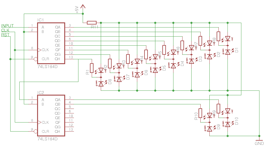
In this case, it will be necessary to select the resistance values of the resistors for a suitable LED glow in cases of red and green LEDs.
After distributing and soldering the following has turned out:

There are 2 shift registers and 10 pairs of LEDs on the debug board. Unfortunately, 4 yellow LEDs in the center of the board are off, very similar to broken register outputs, but enough for debugging.
')
So we have a control circuit for burning LEDs. It is necessary to organize the switching of burning from red to green and back, in any order of registers. An array of bits will be used for this, each bit corresponds to one node and two LEDs: 1 is green and 0 is red. By feeding this sequence of bits to the output of the arduino and clocking each bit with the output CLK, we will write to the registers. To ensure uniqueness, we will reset the registers before each recording of the information by applying a logical zero to the CLR input.
The basis of the code from the "admin traffic light", but does not measure the connection time, but only the fact that it is installed or not installed. A two-dimensional array of node addresses and an array of output data will be used, which will be entered into registers. For ease of debugging, we will check only 5 nodes.
The code is quite simple and with comments:
That's all.
Now it remains to find the right size map of the city, attach the LEDs in the right places and monitor the availability of nodes in real time and not getting up.
Acquainted with the "admin traffic light" the idea of creating an interactive map of the city, with LEDs located on it: red - the node is unavailable, green - available. But if you use the described method of ignition of LEDs, you will need 2 xn, where n is the number of controlled nodes. Thus, to control 10 nodes, 20 pins will be needed. It is clear that this method for solving the problem, in the case of controlling more than 5 nodes, is not suitable.
So, how can you reduce the number of outputs used? From the go to the head comes the use of the decoder. The method is good, but you need to invent your cipher, in which you need to take into account all possible combinations of the work of controlled nodes. The method is good, but not very scalable.
More successful is the method of converting a serial signal into a parallel one. That is, a serial signal goes from the arduino board, and the LED control is already implemented in the additional circuit. Go this way and go.
And so we need:
- develop a scheme for converting a serial signal into a parallel one;
- create an output stage with LEDs to display the status;
- develop an algorithm for recording the necessary information in the scheme;
- implement a network node polling algorithm.
Circuit design
To convert a serial signal, we will use a shift register. At hand was a couple of 74ALS164, so we use them. First of all, we stamp on the manufacturer's website and download the datasheet . This register has:
- CLR reset input;
- CLK clock input;
- 2 signal inputs A and B;
- 8 outputs.
The truth table shows that a reset occurs when the value of the input CLR is zero. Data is written to the register at the front of the CLK signal. The input signal is generated from signals A and B through a logical multiplication (I). Thus, one of the signal inputs, for example B, can be safely brought to the logic level 1. During operation, the presence of a logic unit level at the CLR input is necessary. By controlling the input A you can enter the necessary information in the register. Gating at the CLK input will allow for unambiguous input and output data.
But if we use only 1 microcircuit, then we have only 8 outputs. Yes, not a lot. But then cascading comes to the rescue. That is, if we connect the eighth output of the first register with the input A of the second, then the data will be entered into the second register with a delay of 8 cycles.
Output stage
To control the LEDs, you can use 2 outputs per node, that is, light a red LED or green. But in this case there will be a doubling of the number of registers needed. To avoid this we will use the inclusion of LEDs according to the scheme:
In this case, it will be necessary to select the resistance values of the resistors for a suitable LED glow in cases of red and green LEDs.
After distributing and soldering the following has turned out:
There are 2 shift registers and 10 pairs of LEDs on the debug board. Unfortunately, 4 yellow LEDs in the center of the board are off, very similar to broken register outputs, but enough for debugging.
')
Write algorithm development
So we have a control circuit for burning LEDs. It is necessary to organize the switching of burning from red to green and back, in any order of registers. An array of bits will be used for this, each bit corresponds to one node and two LEDs: 1 is green and 0 is red. By feeding this sequence of bits to the output of the arduino and clocking each bit with the output CLK, we will write to the registers. To ensure uniqueness, we will reset the registers before each recording of the information by applying a logical zero to the CLR input.
Development of the polling node algorithm
The basis of the code from the "admin traffic light", but does not measure the connection time, but only the fact that it is installed or not installed. A two-dimensional array of node addresses and an array of output data will be used, which will be entered into registers. For ease of debugging, we will check only 5 nodes.
The code is quite simple and with comments:
// #define SIG 7 // #define CLK 6 // #define RST 5 // // #include <SPI.h> #include <Ethernet.h> // ethernet shield byte mac[] = {0xDE, 0xAD, 0xBE, 0xEF, 0xFE, 0xED}; // byte ip[] = {192,168,2,177}; // ip // byte pingAddr[][4] = { {172,2,0,5}, {172,2,0,6}, {172,2,0,7}, {172,2,0,8}, {172,2,0,9} }; // bool out[] = {0,0,0,0,0}; // byte gateway[] = {192,168,2,1}; byte subnet[] = {255,255,255,0}; // char buffer[256]; // void checkHost(int i) { Client client(pingAddr[i], 80); // if(!client.connect()) { // sprintf(buffer, "Connection failed for %d.%d.%d.%d", pingAddr[i][0],pingAddr[i][1],pingAddr[i][2],pingAddr[i][3]); Serial.println(buffer); // , if(out[i] == 1) { out[i] = 0; // setMap(); } // } else { // , if(out[i] == 0) { out[i] = 1; setMap(); } } client.stop(); } // void setMap() { // digitalWrite(RST, LOW); delay(5); digitalWrite(RST, HIGH); int i; // for(i=0;i<5;i++) { // 0 if(out[i]==0) digitalWrite(SIG, LOW); // 1 else digitalWrite(SIG, HIGH); // delay(1); // digitalWrite(CLK, HIGH); delay(1); digitalWrite(CLK, LOW); // digitalWrite(SIG, LOW); } } void setup() { // ethernet shield Ethernet.begin(mac, ip, gateway, subnet); // Serial.begin(9600); // / pinMode(SIG, OUTPUT); // signal pinMode(CLK, OUTPUT); // CLK pinMode(RST, OUTPUT); // reset // digitalWrite(CLK, LOW); digitalWrite(SIG, LOW); digitalWrite(RST, HIGH); } // void loop() { int i; // for(i=0;i<5;i++){ // checkHost(i); delay(1000); } // 5 , delay(5000); } That's all.
Now it remains to find the right size map of the city, attach the LEDs in the right places and monitor the availability of nodes in real time and not getting up.
Source: https://habr.com/ru/post/113526/
All Articles