Designing a computer case in CATIA V6
 What is common between the Russian supercar Marussia and the Boeing 777? When developing these and many other products, as well as creating a “virtual copy” of the pyramid of Cheops and modeling the process of melting of the iceberg, Dassault Systèmes solutions are used. Honestly, I never liked too vague the notion of a “solution”, but it is difficult to call what programs in Dassault Systèmes “programs” are. These are huge software systems that solve any problems associated with the development, design and production. From the initial list of requirements for the product (whether it is a bottle for mineral water or a spacecraft) to virtual tests of the finished sample. From control over the execution of the project to taking into account feedback from owners of the previous model. Finally, DS solutions can provide remote access and collaboration of thousands of employees of a large manufacturing company with branches around the world. But there is, however, free 2D CAD for everyone .
To understand this huge and not too familiar to the average user the amount of software is quite difficult. CATIA’s 3D design system alone contains about 200 modules for different production areas, each of which takes into account the properties of metals, the parameters of finished electronic components and much more. And at the same time, everything possible was done to simplify the life of the developer or designer as much as possible. In this article I will show how the finished product is created in practice. Unfortunately, Dassault Systemes customers usually do not share their latest developments - this is their trade secret - therefore, the company's engineers create their own demonstration models. For the first material in the Dassault Systemes blog on Habré, I chose the most interesting and well-known model for most users - the computer case. With the process of designing its parts - the back wall - I want to introduce you.
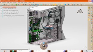
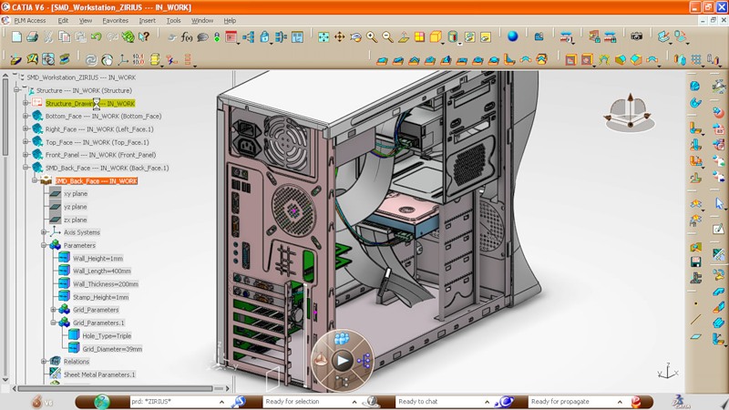
So, we already have an almost finished model of the computer case assembly: with a motherboard, a processor, a hard disk, and cables inside.
')

What is missing is the rear wall of the casing, but a 2D skeleton is already ready for it, in which the location and shape of the required holes are indicated. Everything else - the shape of the wall, mount to the body, etc. - we have to create.
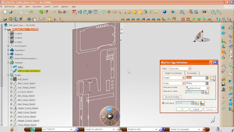
The part must be made of one metal sheet. To begin with, we add side edges on each side of the wall, specifying a bend angle (90 degrees) and width (18 millimeters).

This is what we get as a result. The next step: we create a flange that will become one of the fastening elements of the back wall to the body.
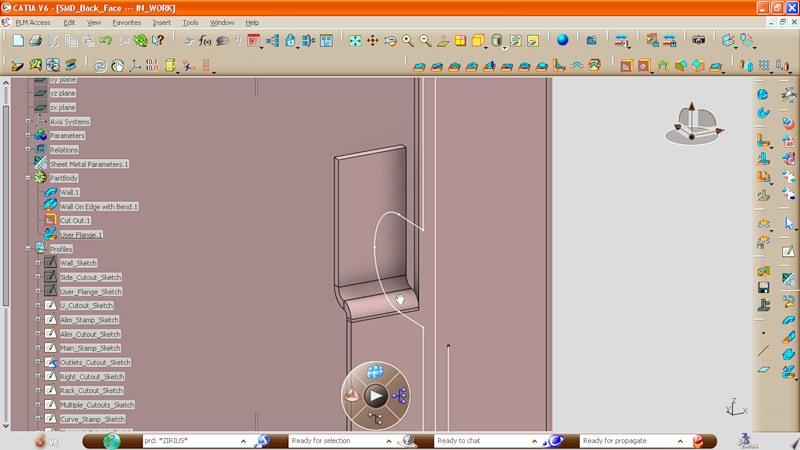
Setting the angle and width, bend the sheet of metal along the edge.
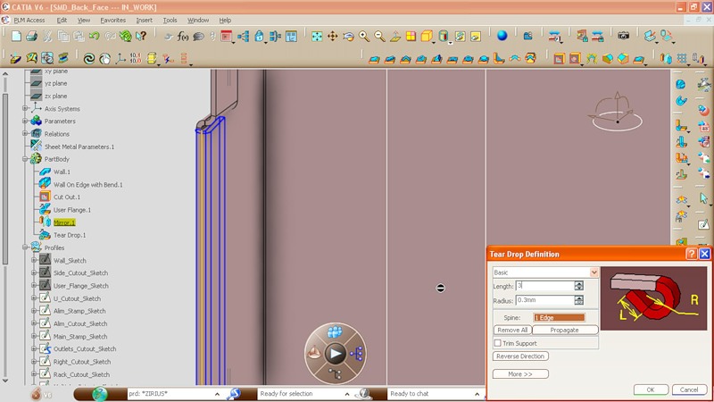
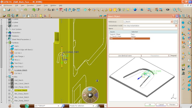
Here, using the punching operation, we create a cut-out that will ensure a tight fit of the back wall to the computer case. It should be noted that the cutout parameters are taken from the library: it can be a library of standard elements from both the corpus developer and the company that will directly deal with the production of the part.
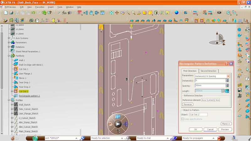
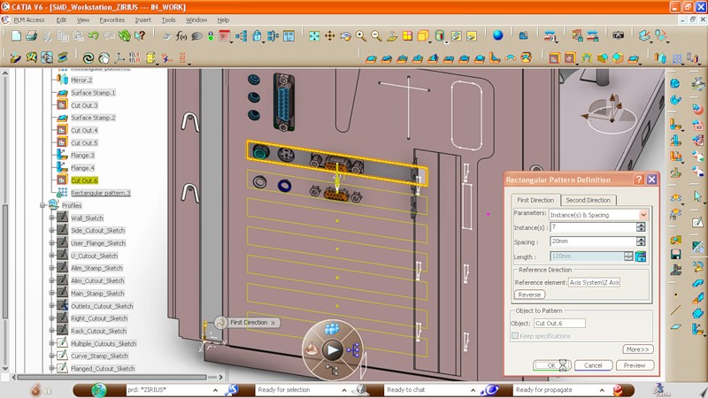
And here you can see how the design process in CATIA can be greatly simplified. Using the standard tool (array), the cut created by us is “duplicated” along the entire length of the part, with a specified interval.
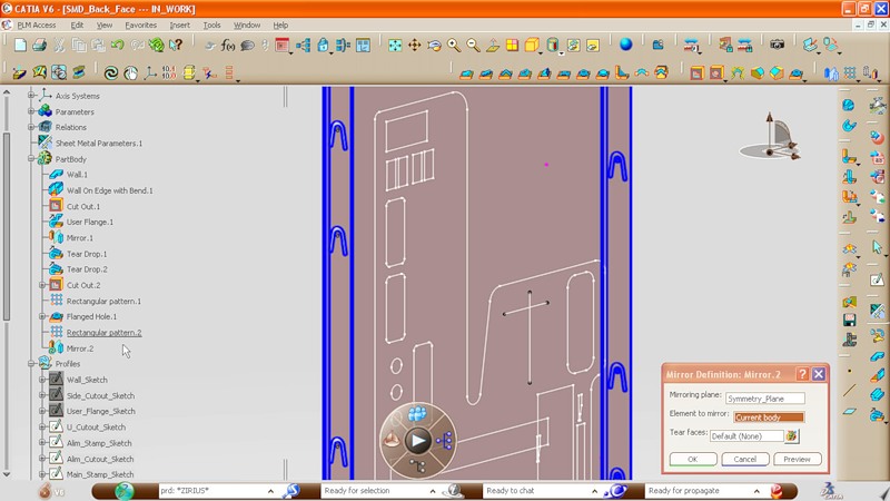
One notch in the middle of the body is removed, and then with the help of another tool (mirror) we symmetrically reflect the changes. Thus, cuts appear on the opposite edge.
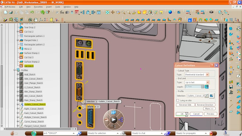
We turn to the creation of holes on the back wall. The contours of these holes are already set, so the cutout for the power supply is created in a couple of clicks.

Do the same with the holes for the connectors on the motherboard.
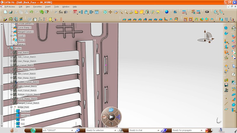
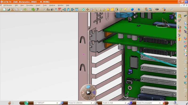
With holes for expansion cards, everything is somewhat more complicated. In the original drawing, there is only one hole for the topmost board. After setting the interval, we create several cuts in a row.
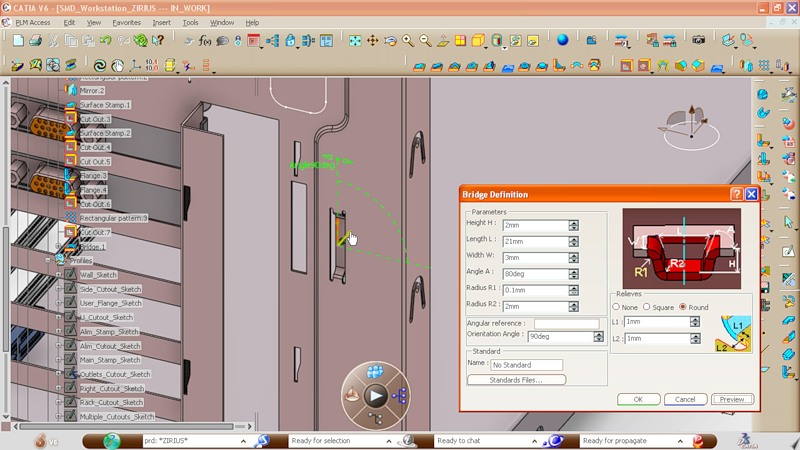
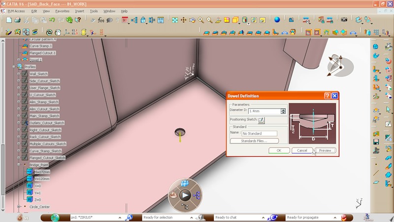
Another small detail, which, apparently, will serve as a fastener for the cover that covers the compartment with expansion cards. Again, take the standard part and set the necessary parameters.
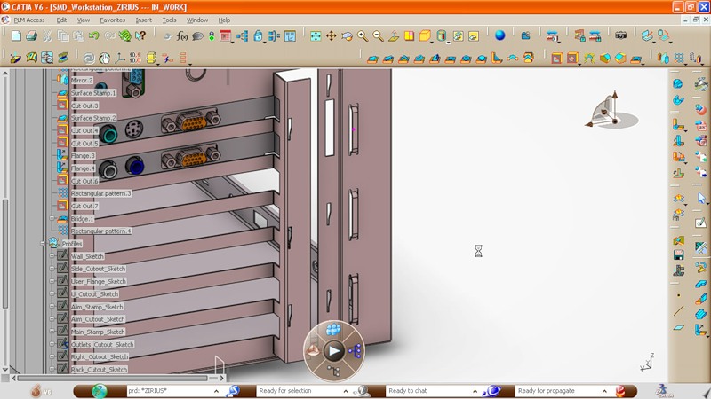
Duplicate mounts and this is what we get as a result:
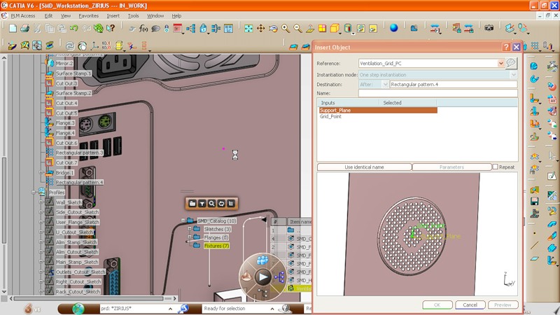
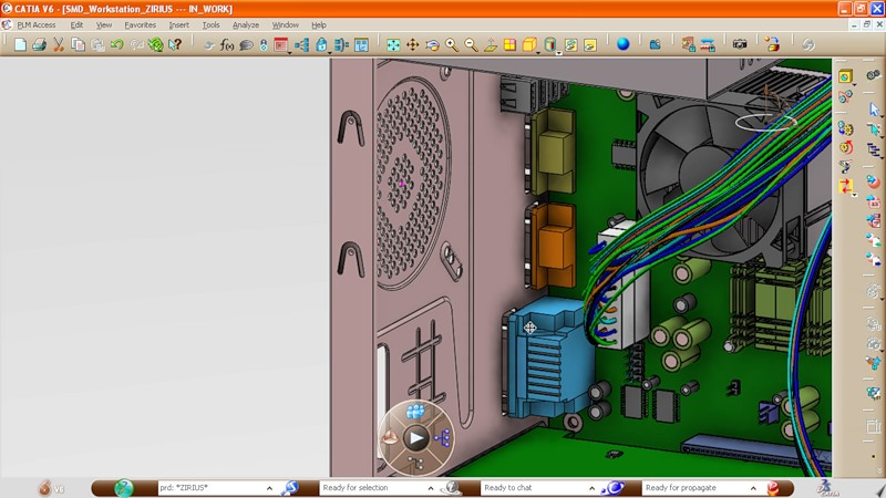
Next, create a ventilation grill for a regular fan on the back wall. There is also no need to specify the location of each hole: the part is simply taken from the library and adjusted to size during the creation process.
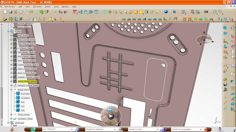
And now in the original drawing will have to make some changes. Initially, in our case, some kind of stiffening ribs were provided:

Go to the sketch mode and add additional elements to this design:

Here is the result:
Left a little. Add fixing stamps on the back wall edge:
And analyze the resulting model:
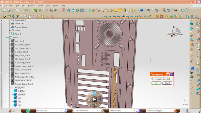
We find one mistake: the width of the panel on which the expansion cards will be mounted is too large. Since the rear wall of the case is made of one sheet of metal, it is physically impossible. Reduce the width of the panel:
And we look what happened on the general model of the computer case:
Inside view:
And further:
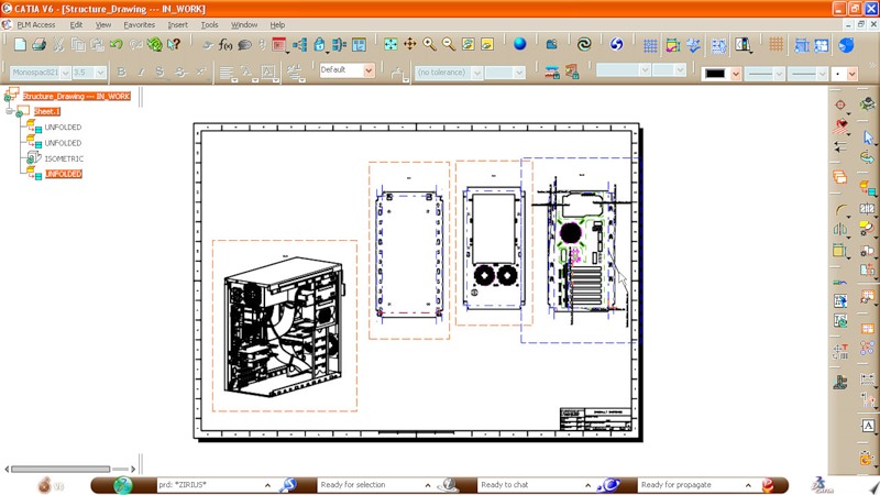
It remains only to translate our 3D model into a regular drawing that can be sent to production. It should be noted that it is no longer necessary to use classical drawings. Most often, it is the 3D model of the part that is sent to the factory.
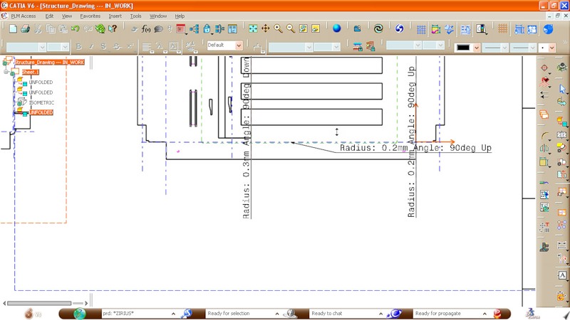
General drawing of the case walls: rear, front, top and bottom.
This video shows the whole process of modeling the back wall. It is best to open it at this link and view in 720p mode.
A lot has been done in CATIA V6 to make the design process as simple as possible. At the same time, this example clearly shows how many small details and nuances exist even in such a simple model. A convenient case, which can be disassembled without a screwdriver, with removable hard drive bays and other things, will require much more power and attention from the developer.
Source: https://habr.com/ru/post/113140/
All Articles