Computer control with variable resistor
What and why?
Recently I read Mikhail Sannikov's article “ Connecting Encoder to Computer ”. And it so happened that the other day they sent me an Arduino board, so I wanted to repeat this simple design or do something similar,
First, a little about what an encoder is and why it is needed at all. An encoder is an angle-to-code converter, the output of which is the gray code. There are input devices built on encoders and outwardly looking like a massive puck, rotating which, for example, you can rotate the model in a 3D editor.

(picture from here )
')
However, I did not have an encoder, I did not want to go to the store, so instead of it, it was decided to adapt the old 150 KΩ variable resistor, which was lying idle in a box with different trash.
So, it was necessary to do the following:
- Connect a variable resistor to the Arduino;
- Make a program for the controller that reads a byte from the analog port and sends it to the computer;
- Write a computer program that emulates pressing certain keys depending on the direction of rotation of the variable resistor shaft.
Hard and soft
An example of Analog In, Out Serial, completely solving the first and second problems, was found in the programming manual on the Arduino website.
The resistor is connected according to the following scheme:

However, the code had to be slightly modified: remove all lines from Serial.print and replace it with one Serial.write (outputValue):
const int analogInPin = A0; // A0
int sensorValue = 0; // ,

void setup() {
Serial.begin(9600); // COM-
}

// A0 COM-
void loop() {
sensorValue = analogRead(analogInPin);
outputValue = map(sensorValue, 0, 1023, 0, 255);
Serial.write(outputValue);
delay(10);
}
The computer control program was written in C # in Visual Studio 2010 Express.
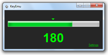
Main program window:
Dialog box with settings:
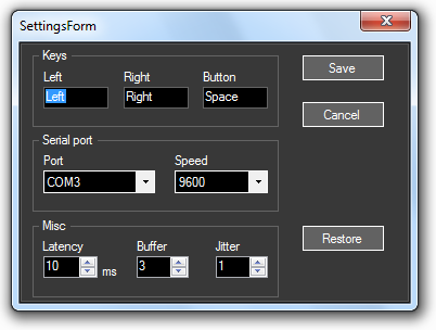
Note: pressing the “Button” button is not processed yet.
Here it is worth considering the parameters from the “Misc” group in more detail. The first is needed to emulate a keystroke, the rest - to eliminate bounce.
Latency - the delay in milliseconds between pressing a key and releasing.
Buffer - the number of consecutively read values from the COM port.
Jitter - shows the permissible deviation from the value of the last sample.
Chatter suppression and determining the direction of rotation of the variable resistor shaft works as follows:
- The buffer reads a certain number of bytes (parameter Buffer) from the serial port;
- if the last byte in the buffer is greater than the sum of the first byte and the Jitter value, this means that the shaft rotates to the right;
- if the last byte in the buffer is less than the difference of the first byte and the Jitter value, this means that the shaft rotates to the left.
The disadvantages of this method:
- the delay between the start of the shaft rotation and the program response to it;
- the key is pressed once, regardless of the angle of rotation. That is, you can quickly turn the resistor shaft (the first byte in the buffer will be, say, 10, and the last - 30), and the program will work it out as one press.
Algorithm code:
int[] buffer = new int[(int)conf.buffer]; // Buffer
int bufferTop = (int)conf.buffer - 1;

for (int i = 0; i < conf.buffer; i++)
{
buffer[i] = sp.ReadByte();
}

if (buffer[bufferTop] > (buffer[0] + conf.jitter))
{
// “”
}
else if (buffer[bufferTop] < (buffer[0] - conf.jitter))
{
// “”
}
The project for Visual Studio, the sketch for Arduino and the scheme can be downloaded here: http://sourceforge.net/projects/keyemu/files/KeyEmu-0.1b-source.zip/download
The archive contains the bin directory containing the compiled program. To run it, you will need the .NET Framework 4 installed.
That's all for now. A curious person can modify the program - implement the processing of a series of clicks instead of one, or “press” different keys depending on which application is active at a given time, or simply “polish this bug” indefinitely.
Source: https://habr.com/ru/post/113029/
All Articles