Operational Amplifiers (Based on Simplest Examples): Part 2
Instead of a boring entry
Last time I tried to briefly explain the basic principles of operation of operational amplifiers. But I just can not refuse to request a continuation of the topic. This time the schemes are a bit more complicated, but I will try not to stretch the tedious mathematical conclusions.
Integrators and differentiators
Imagine that you have to consider the voltage integral.
So, for these purposes, just need an integrator .
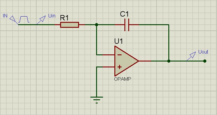
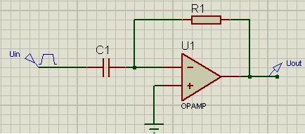
In the general case (for the ideal opamp), this option is considered:
Further, I strongly recommend a little podnipryach and remember a little course of physics and higher mathematics. Although it is not entirely necessary.
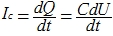
Remember the capacitor charge formula?

Given that the charge will vary in time, we can safely assume:
More ... Non-inverting input is connected to the "ground". The voltage on the capacitor is equal to the opposite voltage at the output, in other words
 . It means that
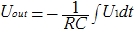
Further, solving and integrating, we obtain the (almost) final formula:
This, so to speak, in general terms. As a result, I want to draw attention to the fact that the output voltage plays a significant role for each time point t. We take it as a free element:
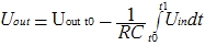
It is logical to assume that the integration goes in time from t0 to t1
')
Here you have a problem. Capacitor discharged. The output voltage is zero. The circuit is off. The capacitor has a capacity of 1 microfarad. 30kΩ resistor. The input voltage is first -2V, then 2V. Polarity changes every second. In other words, we gave a pulse generator to the input.
So we decide. We collect quickly the scheme in Proteus. We draw the schedule. Enter the input and output voltage as functions. Click "Simulate schedule." We get:
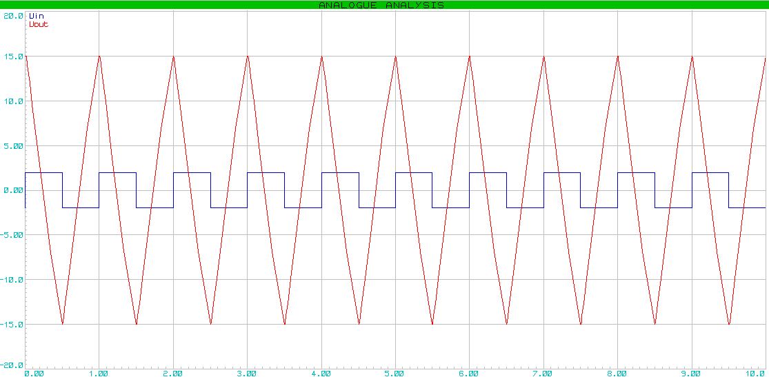
There was a "sawtooth" signal. Please note that the capacitor affects the sharpness of the decline. It should fluctuate within reasonable limits in order to have time to charge / discharge, and not to discharge / discharge * too quickly. By the way, it will be logical to assume that the signal is amplified within the power supply of our op amp.
Next, we turn to the differentiators .
There is no more difficult than in integrators.
Differentiator:
And here is the analog computing formula:

And again the boring formulas ...
The current through the capacitor is equal to

Since the operational amplifier is close to ideal, it can be assumed that the current through the capacitor is equal to the current through the resistor.
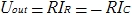 so, if we substitute the current value, we get:
As in the previous example, consider a more practical example. Capacitor with a capacity of 50µF. 30kΩ resistor. At the entrance we give a "saw". (Honestly, in the Proteus it was not possible to make a saw with standard means, I had to resort to the Pwlin tool.
As a result, we get the graph:

Let's sum up.
Integrator. "Rectangle" -> "Saw"
Differentiator. Saw -> Rectangle
PS Differentiators and integrators will be discussed later in a completely different guise.
Comparators
A comparator is a device that compares two input voltages. The state at the output varies in steps, depending on which voltage is higher. There is nothing special, just give an example. At the first input we apply a constant voltage equal to 3V. At the second input is a sinusoidal signal with an amplitude of 4V. Remove the voltage from the output.

The graph contains comprehensive information that does not need comments:

Logarithmic and exponential amplifiers
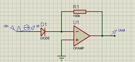
To obtain a logarithmic characteristic, an element possessing it is necessary. For such purposes, a diode or transistor is suitable. In order not to complicate, we will continue to use a diode.
To begin with, as usual, I will give the scheme ...
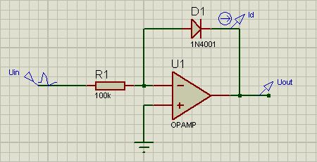
... and the formula:

Note that e is the electron charge, T is the temperature in Kelvin, and k is the Boltzmann constant.
Again have to remember the course of physics. The current through the semiconductor diode can be described as:
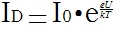 (the image made a bit more, because the degree of the formula turned out "crooked")
Here, U is the diode voltage. I0 is the leakage current at a small reverse bias. Prologue and get:
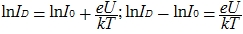
From here we get the voltage on the diode (which is identical to the output voltage):

It is worth making a note that at a temperature of 20 degrees Celsius:

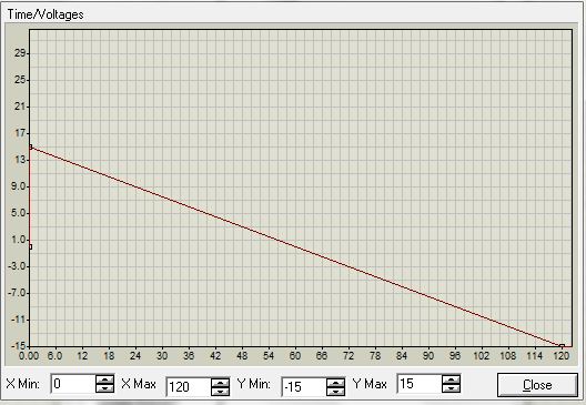
Check how this scheme works graphically. Run the proteus. Set the input:
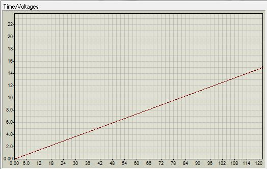
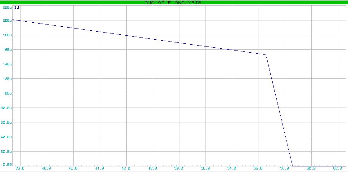
The current on the diode will be changed as follows:

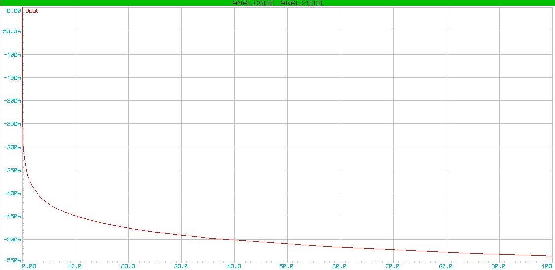
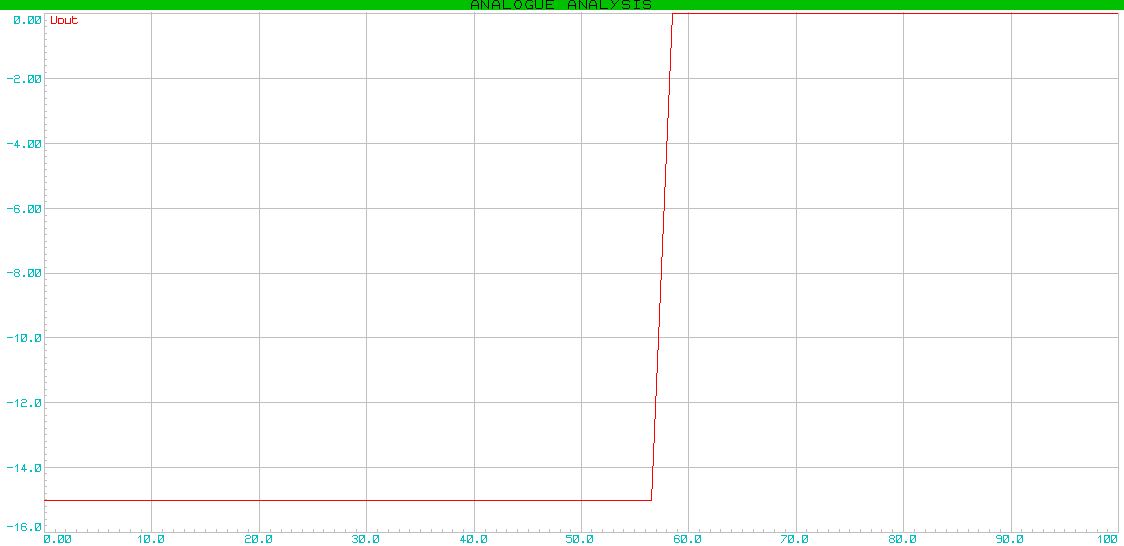
The output voltage varies logarithmically:
The next item is an exponential amplifier I will leave without comment. I hope everything will be clear here.
Instead of conclusion
In this part, I tried to reduce the mathematical conclusions to a minimum, and to focus on practical application. Hope you enjoyed it :-)
* UPD .: The charge / discharge time of a capacitor is defined as:
 where
where  - This is a time of transition. For an RC circuit, the formula is valid.
  . During time T the capacitor will be fully charged / discharged by 99%. Sometimes for calculations use time 3
 Source: https://habr.com/ru/post/112692/
All Articles