Operational Amplifiers (Based on Simplest Examples): Part 1
There are many important topics in the electronics course. Today we will try to deal with operational amplifiers.
Start over. An operational amplifier is such a “thing” that allows you to operate with analog signals in every possible way. The simplest and most basic ones are amplification, weakening, addition, subtraction and many others (for example, differentiation or logarithm). The vast majority of operations on operational amplifiers (OU) are performed using positive and negative feedbacks.
In this article, we will consider a certain "ideal" of the OS, since go to a specific model does not make sense. The ideal implies that the input impedance will tend to infinity (therefore, the input current will tend to zero), and the output impedance - on the contrary, will tend to zero (this means that the load should not affect the output voltage). Also, any ideal opamp should amplify signals of any frequency. Well, and most importantly, the gain when there is no feedback should also tend to infinity.
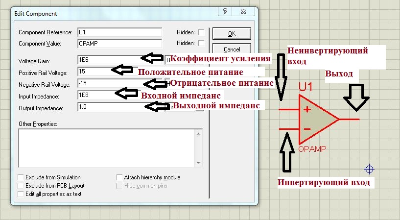
An operational amplifier in circuits is often denoted by an equilateral triangle. On the left are the entrances, which are marked "-" and "+", on the right - the output. The voltage can be applied to any of the inputs, one of which changes the polarity of the voltage (so it was called inverting), the other does not change (it is logical to assume that it is called non-inverting). Nutrition Shelter, most often, bipolar. Usually, the positive and negative supply voltage has the same value (but a different sign!).
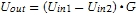
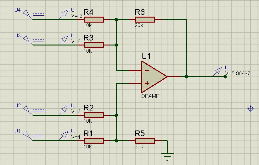
In the simplest case, you can connect the voltage sources directly to the inputs of the OS. And then the voltage at the output will be calculated by the formula:
 where
where  - voltage on non-inverting input,
  - voltage on the inverting input,
  - output voltage and
  - gain without feedback.
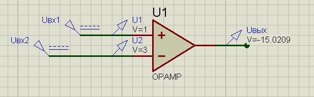
Let's look at the perfect op amp from the point of view of Proteus.
I propose to "play" with him. The non-inverting input was energized at 1V. On the inverting 3B. We use the "perfect" OS. So, we get: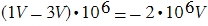 . But here we have a limiter, because we cannot amplify the signal above our supply voltage. Thus, the output will still get -15V. Total:
Change the gain (so that you believe me). Let the Voltage Gain parameter be equal to two. The same problem is clearly solved.

There are two such basic rules:
I. The output of the operational amplifier tends to ensure that the differential voltage (the difference between the voltage on the inverting and non-inverting inputs) is equal to zero.
Ii. OU inputs do not consume current.
The first rule is implemented through feedback. Those. the voltage is transferred from the output to the input in such a way that the potential difference becomes zero.
This, so to speak, "sacred canons" in the subject of the OS.
And now, more specifically. The inverting amplifier looks exactly like this (pay attention to how the inputs are located):

Based on the first "canon" we get the proportion:
 , and a little "conjuring" with the formula, we derive the value for the gain of the inverting opamp:
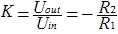
The above screen does not need comments. Just substitute everything yourself and check.
The next stage is a non - inverting amplifier.
It's all just as simple. The voltage is applied directly to the non-inverting input. Feedback is fed to the inverting input. The voltage at the inverting input will be:
 but applying the first rule it can be argued that

And again, the "grandiose" knowledge in the field of higher mathematics allows you to go to the formula:
I will give an exhaustive screen that you can double-check if you want:
')
Finally, I will give a couple of interesting circuits so that you do not have the impression that the opamps can only increase the voltage.
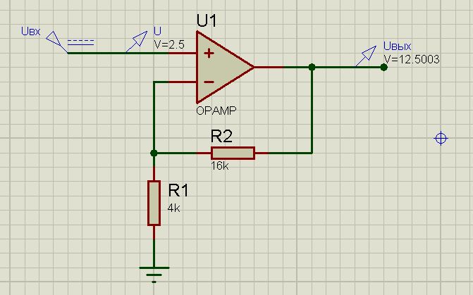
Voltage repeater (buffer amplifier). The principle of operation is the same as that of the transistor follower. Used in chains with a large load. Also, it can be used to solve a problem with matching impedances, if there are unwanted voltage dividers in the circuit. The scheme is simple to genius:
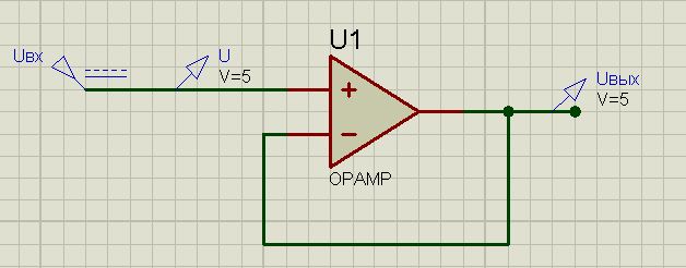
Summing amplifier. It can be used if you want to add (subtract) several signals. For clarity, the scheme (again pay attention to the location of the inputs):
Also, pay attention to the fact that R1 = R2 = R3 = R4, and R5 = R6. The calculation formula in this case will be: (familiar, isn't it?)
Thus, we see that the values of voltages that are fed to the non-inverting input "acquire" a plus sign. On the inverting - minus.
Circuits for operational amplifiers are extremely diverse. In more complex cases, you can find active filter circuits, ADC and storage sampling devices, power amplifiers, current-to-voltage converters, and many many other schemes.
A short list of sources that will help you quickly master both OS and electronics in general:
Wikipedia
P. Horowitz, W. Hill. "The Art of Circuit Engineering"
B. Baker. "What you need to know a digital developer about analog electronics"
Abstract lectures on electronics (preferably your own)
UPD .: Thank you UFO for inviting
Start over. An operational amplifier is such a “thing” that allows you to operate with analog signals in every possible way. The simplest and most basic ones are amplification, weakening, addition, subtraction and many others (for example, differentiation or logarithm). The vast majority of operations on operational amplifiers (OU) are performed using positive and negative feedbacks.
In this article, we will consider a certain "ideal" of the OS, since go to a specific model does not make sense. The ideal implies that the input impedance will tend to infinity (therefore, the input current will tend to zero), and the output impedance - on the contrary, will tend to zero (this means that the load should not affect the output voltage). Also, any ideal opamp should amplify signals of any frequency. Well, and most importantly, the gain when there is no feedback should also tend to infinity.
Closer to the point
An operational amplifier in circuits is often denoted by an equilateral triangle. On the left are the entrances, which are marked "-" and "+", on the right - the output. The voltage can be applied to any of the inputs, one of which changes the polarity of the voltage (so it was called inverting), the other does not change (it is logical to assume that it is called non-inverting). Nutrition Shelter, most often, bipolar. Usually, the positive and negative supply voltage has the same value (but a different sign!).
In the simplest case, you can connect the voltage sources directly to the inputs of the OS. And then the voltage at the output will be calculated by the formula:
where - voltage on non-inverting input, - voltage on the inverting input, - output voltage and - gain without feedback.Let's look at the perfect op amp from the point of view of Proteus.
I propose to "play" with him. The non-inverting input was energized at 1V. On the inverting 3B. We use the "perfect" OS. So, we get:
. But here we have a limiter, because we cannot amplify the signal above our supply voltage. Thus, the output will still get -15V. Total:Change the gain (so that you believe me). Let the Voltage Gain parameter be equal to two. The same problem is clearly solved.
Real application of op amps using the example of inverting and non-inverting amplifiers
There are two such basic rules:
I. The output of the operational amplifier tends to ensure that the differential voltage (the difference between the voltage on the inverting and non-inverting inputs) is equal to zero.
Ii. OU inputs do not consume current.
The first rule is implemented through feedback. Those. the voltage is transferred from the output to the input in such a way that the potential difference becomes zero.
This, so to speak, "sacred canons" in the subject of the OS.
And now, more specifically. The inverting amplifier looks exactly like this (pay attention to how the inputs are located):
Based on the first "canon" we get the proportion:
, and a little "conjuring" with the formula, we derive the value for the gain of the inverting opamp:The above screen does not need comments. Just substitute everything yourself and check.
The next stage is a non - inverting amplifier.
It's all just as simple. The voltage is applied directly to the non-inverting input. Feedback is fed to the inverting input. The voltage at the inverting input will be:
but applying the first rule it can be argued thatAnd again, the "grandiose" knowledge in the field of higher mathematics allows you to go to the formula:
I will give an exhaustive screen that you can double-check if you want:
')
A couple of interesting schemes
Finally, I will give a couple of interesting circuits so that you do not have the impression that the opamps can only increase the voltage.
Voltage repeater (buffer amplifier). The principle of operation is the same as that of the transistor follower. Used in chains with a large load. Also, it can be used to solve a problem with matching impedances, if there are unwanted voltage dividers in the circuit. The scheme is simple to genius:
Summing amplifier. It can be used if you want to add (subtract) several signals. For clarity, the scheme (again pay attention to the location of the inputs):
Also, pay attention to the fact that R1 = R2 = R3 = R4, and R5 = R6. The calculation formula in this case will be:
(familiar, isn't it?)Thus, we see that the values of voltages that are fed to the non-inverting input "acquire" a plus sign. On the inverting - minus.
Conclusion
Circuits for operational amplifiers are extremely diverse. In more complex cases, you can find active filter circuits, ADC and storage sampling devices, power amplifiers, current-to-voltage converters, and many many other schemes.
List of sources
A short list of sources that will help you quickly master both OS and electronics in general:
Wikipedia
P. Horowitz, W. Hill. "The Art of Circuit Engineering"
B. Baker. "What you need to know a digital developer about analog electronics"
Abstract lectures on electronics (preferably your own)
UPD .: Thank you UFO for inviting
Source: https://habr.com/ru/post/112665/
All Articles