Voice control: digital signal processing on 8-bit AVR using a hard assembler
So, it's time to tell something more interesting than simple crafts on AVRkah. In this article I will tell you how to assemble a device on the AVR that performs quite serious audio signal processing in order to recognize voice commands.
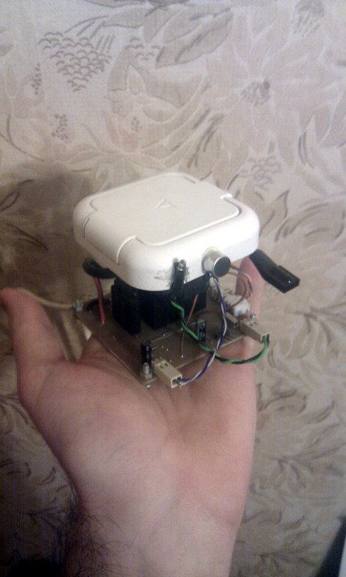
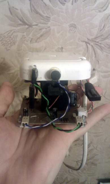
First of all, I would like to show the result to which I arrived.
')
The device is assembled in the gland and is fully functional. The probability of recognition, of course, is very low, but for such a device it is already a great achievement - let me remind you that its core is the ATMega88 8-bit microcontroller, with a frequency of 20 MHz and without any DSP instructions. The device recognizes two teams (the number of teams can be expanded to ten, resources allow), one of which includes the power load, the other - turns it off. In addition, you can turn on-off the load from any IR remote. The device is capable of switching up to 250V / 8A.
For the most part, I designed it out of academic interest in order to check whether it is possible to implement such DSP algorithms on a cheap and low-power general-purpose microcontroller. The result was quite satisfactory, and the device works in my home 24/7.
If we talk about the feasibility of using low-power microcontrollers - I will say briefly: in principle, it is better not to)
For such a task, a younger chip from the dsPIC line, with 16-bit DSP instructions, which are as cheap as AVRs and come with the same small number of legs, is more suitable. Either something from TI from the MSP430F2xxx line
But, if you also like me are interested in what can be squeezed out of the AVR - for you this article.
Let's start with the development of the electrical circuit and try to understand what we need from it.
And you need the following:
1) Power from 220V. In principle, it is possible to power it at least from the batteries, but having at hand 220 volts IMHO a more logical decision to take power from there.
2) Switching the load to 220v / 5A with control from 5V. I took the amps offhand, 5A is already enough to power some fragrant kettle with kilowatt consumption. Or a dozen bulbs in 100 watts)
3) It is desirable additional control, in case the voice fails, or do not want to make a noise.
4) Capture sound with selected parameters. About the parameters a little later.
The first item is trivial - you can put any power supply you know, because circuit consumption is very low. But since it is turned on 24/7, I chose a simple and reliable two-full-power transformer power supply unit consisting of the TPG-0.7 transformer itself, which converts 220V to 12V, a diode bridge, a smoothing capacitor, and two linear voltage regulators that give me a stable 5V and 9V.

Power 5B, of course, goes to the digital schematics. But I needed 9V for the analog part, since the maximum voltage that the LM324 can produce is equal to Epit-1.5 volts. It is not difficult to calculate that when it is powered from 5V, a maximum output of 3.5 can be obtained, this did not suit me.
Go to step two. To switch the load, I chose a reliable and proven solid-state relay S202S02, capable of switching up to 250V8A.
It does not contain any mechanical parts, the switching circuit is extremely simple: the relay has 4 pins - two pins to the load, they are in the “normally open” state. When applied to the control pin log 1, the relay closes and conducts current.
Point 3 is also simple. The integrated infrared sensor TSOP1736 comes to the rescue, which is a small three-foot miracle that connects to the ground and 5V power supply with two pins, respectively, and from the third it generates a log. 1, when there is no input signal, and log 0, when an input signal is detected. The input signal is modulated infrared radiation, with a carrier frequency of 36 kHz, which is close to that of most IR consoles. Due to modulation, TSOP is fairly well protected from extraneous IR noise and constant light, such as solar.
We turn to the most interesting part, part of the audio capture. Immediately present the developed scheme:
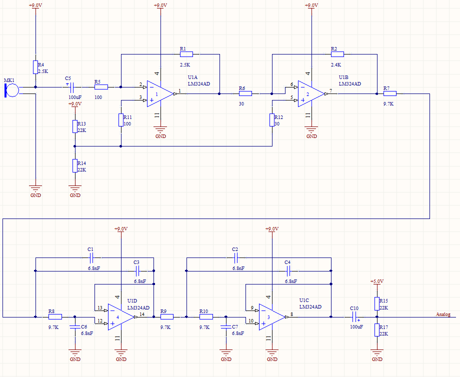
So, as I said, the analog part is powered from 9 volts. The scheme is based on apnotes from Texas Instruments dedicated to the unipolar inclusion of opamps. As an operational amplifier, I chose LM324, a kopek "four core" op amp. You can buy it everywhere, no more than 10 rubles, so the entire analog part is built on a single chip.
The signal from the electret microphone fed through the resistor R4 is fed through the decoupling capacitor to the preamplifier input, and then to the amplifier (upper “floor” of the circuit). The amplifiers are switched on by an inverting unipolar circuit, therefore, half of the supply voltage from the divider is fed to the non-inverting inputs.
After the first amp we get an inverted signal, amplified 25 times and shifted by 4.5 volts. After the second (Conder in front of him is not needed, because for him the “ground” is the same 4.5 volts, to which we have already shifted the signal) the input signal is again inverted and amplified another 80 times.
The total gain of the two stages is 2000, i.e. a bipolar microphone signal of 2 mV will appear before the ADC with a 4-volt signal shifted by half the supply voltage. Exactly what is needed.
I picked up the gain factors for my specific microphone - of course, if your output does not give 2 mV and 20, then the gain should be reduced. And you can completely solder trimmers resistors, and change the gain as needed.
The second "floor" of the scheme is two anti-aliazing filters, made on the Salen-Kay topology, of the second order. Since most of the speech signal lies in low frequencies, I chose a sampling frequency of 5 kHz, which gives us a maximum signal frequency of 2500 Hertz. The filters are tuned to a frequency of about 2KHz, which, in combination with the 4th order, provides excellent anti-ligation filtering.
And the last step is to cut the 4.5V constants coming from the amps using the C10 capacitor and add a new 2.5V constant component to capture the ADC controller, which, of course, is powered from 5V and waits for a signal from 0 to 5V.
The last part of the scheme - the controller with strapping:
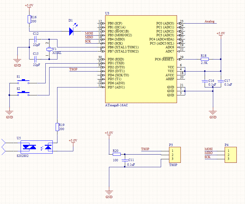
It also shows TSOP1736, a power relay, a pair of control buttons (which I never used in the project), an indicator diode, and a port for programming.
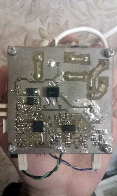
The whole scheme looks like this:
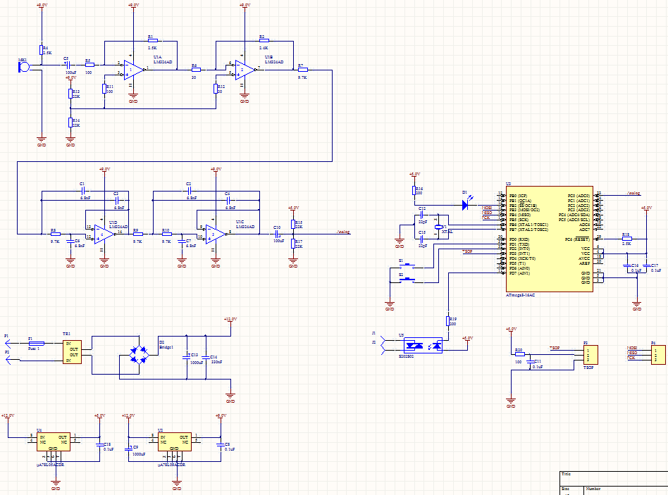
The developed platform turned out to be very convenient for various DSP experiments.
For the analog and digital parts I have not had any complaints for the whole time of testing and use. But with the power I was slightly mistaken - I took a transformer for 12V, I did not take into account that it gives out 12 volts at nominal load (about 100 mA). And since the circuit consumes a lot less, the transformer produces not 12 but about 15 volts, which is why linear stabilizers heat up, especially the one on 5V - because on it falls a dozen.
Otherwise, the circuit turned out to be very successful, and I often use the similar analog part in my projects. Since the controller is set to 20 MHz, and the sampling frequency is 5 KHz, it has 4000 clock cycles for digital signal processing.
That's all for now, in the next part of the article I will tell about the recognition algorithm implemented by me. To save clock cycles, it was implemented in pure assembler, so get ready)
First of all, I would like to show the result to which I arrived.
')
The device is assembled in the gland and is fully functional. The probability of recognition, of course, is very low, but for such a device it is already a great achievement - let me remind you that its core is the ATMega88 8-bit microcontroller, with a frequency of 20 MHz and without any DSP instructions. The device recognizes two teams (the number of teams can be expanded to ten, resources allow), one of which includes the power load, the other - turns it off. In addition, you can turn on-off the load from any IR remote. The device is capable of switching up to 250V / 8A.
For the most part, I designed it out of academic interest in order to check whether it is possible to implement such DSP algorithms on a cheap and low-power general-purpose microcontroller. The result was quite satisfactory, and the device works in my home 24/7.
If we talk about the feasibility of using low-power microcontrollers - I will say briefly: in principle, it is better not to)
For such a task, a younger chip from the dsPIC line, with 16-bit DSP instructions, which are as cheap as AVRs and come with the same small number of legs, is more suitable. Either something from TI from the MSP430F2xxx line
But, if you also like me are interested in what can be squeezed out of the AVR - for you this article.
Circuitry
Let's start with the development of the electrical circuit and try to understand what we need from it.
And you need the following:
1) Power from 220V. In principle, it is possible to power it at least from the batteries, but having at hand 220 volts IMHO a more logical decision to take power from there.
2) Switching the load to 220v / 5A with control from 5V. I took the amps offhand, 5A is already enough to power some fragrant kettle with kilowatt consumption. Or a dozen bulbs in 100 watts)
3) It is desirable additional control, in case the voice fails, or do not want to make a noise.
4) Capture sound with selected parameters. About the parameters a little later.
The first item is trivial - you can put any power supply you know, because circuit consumption is very low. But since it is turned on 24/7, I chose a simple and reliable two-full-power transformer power supply unit consisting of the TPG-0.7 transformer itself, which converts 220V to 12V, a diode bridge, a smoothing capacitor, and two linear voltage regulators that give me a stable 5V and 9V.
Power 5B, of course, goes to the digital schematics. But I needed 9V for the analog part, since the maximum voltage that the LM324 can produce is equal to Epit-1.5 volts. It is not difficult to calculate that when it is powered from 5V, a maximum output of 3.5 can be obtained, this did not suit me.
Go to step two. To switch the load, I chose a reliable and proven solid-state relay S202S02, capable of switching up to 250V8A.
It does not contain any mechanical parts, the switching circuit is extremely simple: the relay has 4 pins - two pins to the load, they are in the “normally open” state. When applied to the control pin log 1, the relay closes and conducts current.
Point 3 is also simple. The integrated infrared sensor TSOP1736 comes to the rescue, which is a small three-foot miracle that connects to the ground and 5V power supply with two pins, respectively, and from the third it generates a log. 1, when there is no input signal, and log 0, when an input signal is detected. The input signal is modulated infrared radiation, with a carrier frequency of 36 kHz, which is close to that of most IR consoles. Due to modulation, TSOP is fairly well protected from extraneous IR noise and constant light, such as solar.
We turn to the most interesting part, part of the audio capture. Immediately present the developed scheme:
So, as I said, the analog part is powered from 9 volts. The scheme is based on apnotes from Texas Instruments dedicated to the unipolar inclusion of opamps. As an operational amplifier, I chose LM324, a kopek "four core" op amp. You can buy it everywhere, no more than 10 rubles, so the entire analog part is built on a single chip.
The signal from the electret microphone fed through the resistor R4 is fed through the decoupling capacitor to the preamplifier input, and then to the amplifier (upper “floor” of the circuit). The amplifiers are switched on by an inverting unipolar circuit, therefore, half of the supply voltage from the divider is fed to the non-inverting inputs.
After the first amp we get an inverted signal, amplified 25 times and shifted by 4.5 volts. After the second (Conder in front of him is not needed, because for him the “ground” is the same 4.5 volts, to which we have already shifted the signal) the input signal is again inverted and amplified another 80 times.
The total gain of the two stages is 2000, i.e. a bipolar microphone signal of 2 mV will appear before the ADC with a 4-volt signal shifted by half the supply voltage. Exactly what is needed.
I picked up the gain factors for my specific microphone - of course, if your output does not give 2 mV and 20, then the gain should be reduced. And you can completely solder trimmers resistors, and change the gain as needed.
The second "floor" of the scheme is two anti-aliazing filters, made on the Salen-Kay topology, of the second order. Since most of the speech signal lies in low frequencies, I chose a sampling frequency of 5 kHz, which gives us a maximum signal frequency of 2500 Hertz. The filters are tuned to a frequency of about 2KHz, which, in combination with the 4th order, provides excellent anti-ligation filtering.
And the last step is to cut the 4.5V constants coming from the amps using the C10 capacitor and add a new 2.5V constant component to capture the ADC controller, which, of course, is powered from 5V and waits for a signal from 0 to 5V.
The last part of the scheme - the controller with strapping:
It also shows TSOP1736, a power relay, a pair of control buttons (which I never used in the project), an indicator diode, and a port for programming.
The whole scheme looks like this:
The results of the development of schematics
The developed platform turned out to be very convenient for various DSP experiments.
For the analog and digital parts I have not had any complaints for the whole time of testing and use. But with the power I was slightly mistaken - I took a transformer for 12V, I did not take into account that it gives out 12 volts at nominal load (about 100 mA). And since the circuit consumes a lot less, the transformer produces not 12 but about 15 volts, which is why linear stabilizers heat up, especially the one on 5V - because on it falls a dozen.
Otherwise, the circuit turned out to be very successful, and I often use the similar analog part in my projects. Since the controller is set to 20 MHz, and the sampling frequency is 5 KHz, it has 4000 clock cycles for digital signal processing.
That's all for now, in the next part of the article I will tell about the recognition algorithm implemented by me. To save clock cycles, it was implemented in pure assembler, so get ready)
Source: https://habr.com/ru/post/111823/
All Articles