Development of a touch keyboard for their devices
In this article I will describe the process of developing a touch-sensitive keyboard that can be used in my devices. Such a keyboard is easy to assemble, because there are no mechanical parts, and the lack of mechanical feedback is compensated by the elegance of use.
In the process of developing one project, I needed a comfortable keyboard with 8 buttons. I decided to resort to the well-known approach - to implement capacitive sensors.
I have already described the physical theory in my article about a souvenir device I felt when taking it in my hand ( http://habrahabr.ru/blogs/DIY/111627/ )
The principle remains exactly the same, the only difference in the implementation is that not one of the microcontroller outputs is used, but one.
For a start, a video of what we will strive for:
')
The sensor circuitry has slightly changed, due to the fact that it is necessary to use only one leg of the microcontroller per sensor, and not two. However, if you do not mind the extra legs, then you can leave everything as before.
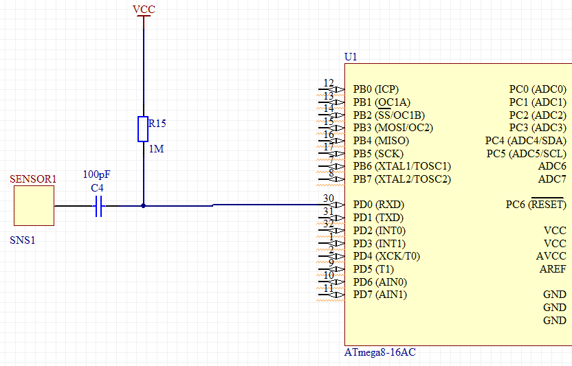
The polling order of the sensor will be slightly different. Initially, a PD0 file has a log. 0
Thus, the current flows from the power source through the megohm resistor and flows into the pin. If the sensor was charged, then the current from it will also flow to pin PD0.
At the time of the survey, we switch the pin from the output to the input (the suspenders are disabled!). At this moment, the pin goes into a high-impedance state, with a resistance of the order of several tens (or even hundreds) of MOM. The current in the direction of the pin practically stops flowing, and begins to flow towards the sensor. As soon as the sensor is charged to a voltage above the level of the log. 1, this microcontroller input will show the unit.
Measuring the time that has passed since the PD0 was transferred to a high-impedance state before the appearance of log 1 on it, we can conclude that the sensor capacitance has changed, which means that the moment of touch is caught.
Structurally, the sensor is a rectangular contact pad 10x10 mm, but in fact its shape is almost unlimited, you can make circles, snakes, divide them into segments and sectors - in general, entering information in any form.
Below is a picture of the finished PCB. The fee is customized, but to make one at home is also not difficult. When using prototyping boards, a piece of foiled fiberglass laminate glued over the board can act as a sensor.

Above each sensor is a SMD diode to indicate depression.
All of this is controlled by an ATMega88 microcontroller set at 20 MHz.
Thus, the output from this keyboard can be made by anyone, which one you will need and which one will pull mega. In my case, SPI was convenient (I was flashing and testing without disconnecting from the programmer, and the device already had this bus involved), but you can use the built-in mega on a par with SPI UART, I2C, or use the ObjDev USB software implementation. Yes, in fact, it is possible and hardware, type FTDI converter USB-> UART.
The final diagram (screenshot from Altium) is presented below.
Again, nothing complicated, nothing superfluous — a mega clocking circuit, a pair of power-smoothing conders, a programming / connecting connector, 8 diodes and 8 sensors.
What is interesting: the distance at which the sensor can feel the hand depends on the bit depth of the timer, its frequency, as well as the resistance through which the sensor is connected. The reason is simple - a faster timer will be able to detect smaller time intervals, and in the absence of galvanic contact with the sensor the charging time is significantly reduced. A 20 MHz mega and its 16-bit timer is enough to reliably detect a touch through a layer of plastic (plexiglass) of about 1 mm.
You can slightly overclock mega and slightly increase the resistance, but it’s better not to get carried away - the stability of the overclocked mega is not guaranteed, and too much resistance can equalize the charge current with the leakage current, which will make the sensor always inactive.
Anyway, the normal mode of operation is quite enough to cover the sensors with a thin piece of plastic. The ideal option would be to spray the conductive coating on the glass, but I did not have much opportunity to experiment in this direction.
Next is the code.
In principle, everything is already described above, but for some clarity I will give the project code.
In the process of developing one project, I needed a comfortable keyboard with 8 buttons. I decided to resort to the well-known approach - to implement capacitive sensors.
I have already described the physical theory in my article about a souvenir device I felt when taking it in my hand ( http://habrahabr.ru/blogs/DIY/111627/ )
The principle remains exactly the same, the only difference in the implementation is that not one of the microcontroller outputs is used, but one.
For a start, a video of what we will strive for:
Step 1: Circuitry
')
The sensor circuitry has slightly changed, due to the fact that it is necessary to use only one leg of the microcontroller per sensor, and not two. However, if you do not mind the extra legs, then you can leave everything as before.
The polling order of the sensor will be slightly different. Initially, a PD0 file has a log. 0
Thus, the current flows from the power source through the megohm resistor and flows into the pin. If the sensor was charged, then the current from it will also flow to pin PD0.
At the time of the survey, we switch the pin from the output to the input (the suspenders are disabled!). At this moment, the pin goes into a high-impedance state, with a resistance of the order of several tens (or even hundreds) of MOM. The current in the direction of the pin practically stops flowing, and begins to flow towards the sensor. As soon as the sensor is charged to a voltage above the level of the log. 1, this microcontroller input will show the unit.
Measuring the time that has passed since the PD0 was transferred to a high-impedance state before the appearance of log 1 on it, we can conclude that the sensor capacitance has changed, which means that the moment of touch is caught.
Structurally, the sensor is a rectangular contact pad 10x10 mm, but in fact its shape is almost unlimited, you can make circles, snakes, divide them into segments and sectors - in general, entering information in any form.
Below is a picture of the finished PCB. The fee is customized, but to make one at home is also not difficult. When using prototyping boards, a piece of foiled fiberglass laminate glued over the board can act as a sensor.
Above each sensor is a SMD diode to indicate depression.
All of this is controlled by an ATMega88 microcontroller set at 20 MHz.
Thus, the output from this keyboard can be made by anyone, which one you will need and which one will pull mega. In my case, SPI was convenient (I was flashing and testing without disconnecting from the programmer, and the device already had this bus involved), but you can use the built-in mega on a par with SPI UART, I2C, or use the ObjDev USB software implementation. Yes, in fact, it is possible and hardware, type FTDI converter USB-> UART.
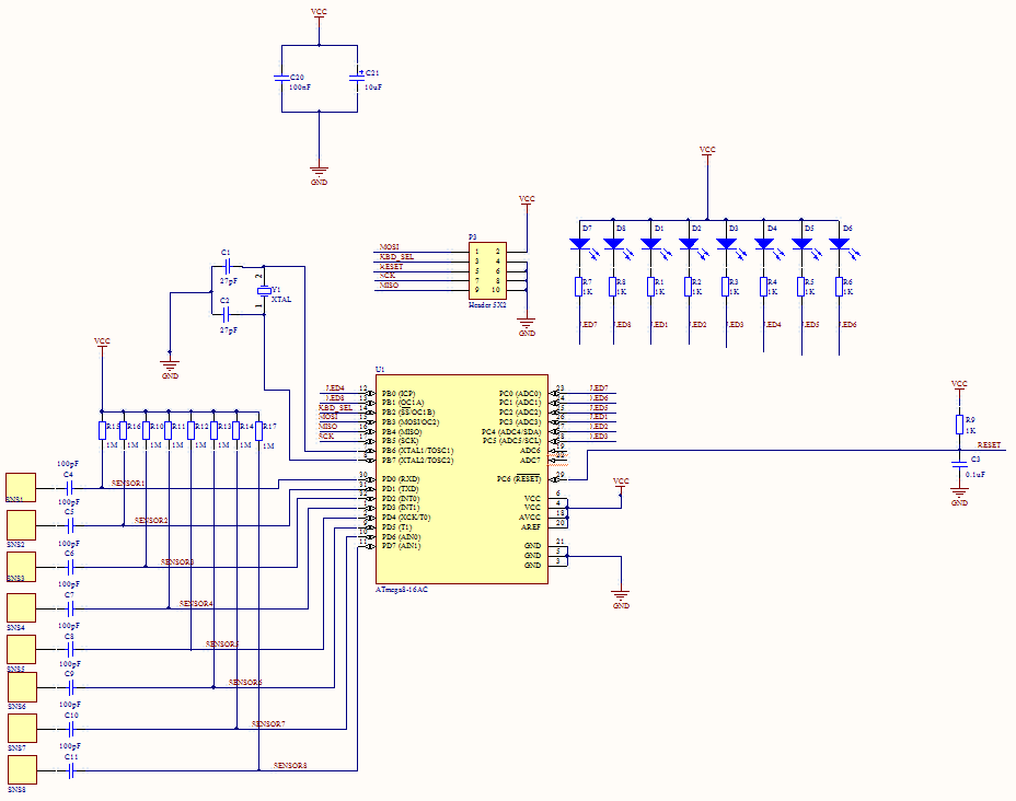
The final diagram (screenshot from Altium) is presented below.
Again, nothing complicated, nothing superfluous — a mega clocking circuit, a pair of power-smoothing conders, a programming / connecting connector, 8 diodes and 8 sensors.
What is interesting: the distance at which the sensor can feel the hand depends on the bit depth of the timer, its frequency, as well as the resistance through which the sensor is connected. The reason is simple - a faster timer will be able to detect smaller time intervals, and in the absence of galvanic contact with the sensor the charging time is significantly reduced. A 20 MHz mega and its 16-bit timer is enough to reliably detect a touch through a layer of plastic (plexiglass) of about 1 mm.
You can slightly overclock mega and slightly increase the resistance, but it’s better not to get carried away - the stability of the overclocked mega is not guaranteed, and too much resistance can equalize the charge current with the leakage current, which will make the sensor always inactive.
Anyway, the normal mode of operation is quite enough to cover the sensors with a thin piece of plastic. The ideal option would be to spray the conductive coating on the glass, but I did not have much opportunity to experiment in this direction.
Next is the code.
Step 2: Code
In principle, everything is already described above, but for some clarity I will give the project code.
#include <avr/interrupt.h> #include <avr/io.h> unsigned char KBD_STATUS=0x00, TMP_STATUS=0x00; // , unsigned short SensorTimes[8]={0,0,0,0,0,0,0,0}; // unsigned short SensorHI[8]={0,0,0,0,0,0,0,0}, // - SensorLO[8]={0,0,0,0,0,0,0,0}; // void CheckSensors(); unsigned short SensToLED[8]={8,16,32,1,4,2,1,2}; //. , .. ) ISR(TIMER0_OVF_vect) { CheckSensors(); // for(unsigned short i=0;i<8;i++) { if(KBD_STATUS&(1<<i)==0) // . , if(i==3||i==7) PORTB|=SensToLED[i]; // . else PORTC|=SensToLED[i]; // . else if(i==3||i==7) PORTB|=SensToLED[i]; else PORTC&=~SensToLED[i]; } } ISR(SPI_STC_vect) // SPI { SPDR=KBD_STATUS; // ! } void InitSPIMode3() // SPI { DDRB= 0b00010011; PORTB=0b00000011; SPCR= 0b11001100; SPSR=0x00; } void Calibrate() // { unsigned char i=1,k=0; while(i!=0) { TCNT1=0x0000; TCCR1B=0x01; DDRD = ~i; while((PIND&i)==0); TCCR1B=0x00; DDRD|=i; SensorTimes[k]=TCNT1; SensorHI[k]=SensorTimes[k]+70; SensorLO[k]=SensorTimes[k]+20; k++; i<<=1; } } void CheckSensors() // { unsigned char i=1,k=0; TMP_STATUS=KBD_STATUS; TCNT1=0x0000; TCCR1B=0x01; DDRD = 0b11111110; while(i!=0) { TCNT1=0x0000; TCCR1B=0x01; DDRD = ~i; while((PIND&i)==0); TCCR1B=0x00; DDRD|=i; if(TCNT1>SensorHI[k]) //, TMP_STATUS|=i; else if(TCNT1<=SensorLO[k]) TMP_STATUS&=~i; k++; i<<=1; } KBD_STATUS=TMP_STATUS; } int main() { DDRD=0xFF; PORTD=0x00; PORTC=0xFF; DDRC=0xFF; TCCR0=0b00000101; TCNT0=0x00; TCCR1A=0x00; TCCR1B=0x00; TCNT1H=0x00; TCNT1L=0x00; ICR1H=0x00; ICR1L=0x00; OCR1AH=0x00; OCR1AL=0x00; OCR1BH=0x00; OCR1BL=0x00; ASSR=0x00; TCCR2=0x00; TCNT2=0x00; OCR2=0x00; MCUCR=0x00; TIMSK=0x01; ACSR=0x80; SFIOR=0x00; InitSPIMode3(); for(int i=0;i<1024;i++) // CheckSensors(); // ) KBD_STATUS=0x00; TMP_STATUS=0x00; Calibrate(); // sei(); while(1); } Source: https://habr.com/ru/post/111679/
All Articles