We create an original gift with the help of chemistry, physics and electronics: part 2
In the previous part ( http://habrahabr.ru/blogs/DIY/111610/ ) the first step towards the creation of the device, the actual growth of the crystal, was considered. In this part we will consider the physical embodiment of the device itself and its electrical circuit.
The long and dreary part is over, now everything will go faster. After I received my crystal, I wondered “where can I get a suitable glass cylinder in which the crystal can be concluded?” The answer was found in the store “everything for the home”, in the form of an excellent cylindrical stack for vodka costing 20 rubles per piece.

')
She attracted me for two reasons: firstly, she was without patterns, engravings and the correct form - an even glass cylinder. Secondly, it was rather thick-walled, which has a good effect on the strength of the structure.
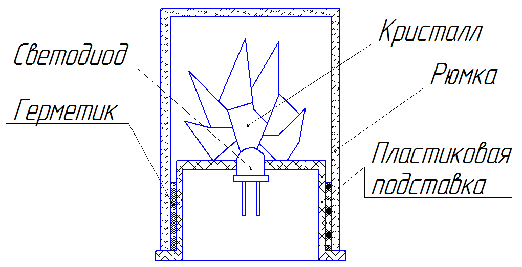
The final construction to which we must come is shown below.
In principle, if you have grown a fist-sized crystal, or you simply do not like such stacks, you can choose any suitable transparent container. The main thing is to be able to seal it in consequence to prevent the weathering of the crystal.
Now our task is to find a plastic insert hollow inside, on which a crystal can be placed, and inside it a control circuit with a battery. I stopped at a plastic rosin box, which ideally entered the glass.
In the center of it we make a hole under the LED (in more detail on the choice of the LED I will focus on the part devoted to electronics), insert it there and seal it from the inside with a hot-melt gun. On the same glue, we plant a crystal outside a plastic stand, directly above the LED.
Making sure that everything is exactly as it should be, we proceed to the final stage of this step - we lubricate the outer surface of the stand with a sealant of a suitable color (I chose the black stand, respectively, and the black sealant) and insert it inside the glass. After the sealant hardens, you will have a completely sealed glass with a crystal inside, which can be highlighted by supplying power to the LED terminals.
I did not fill the crystal with anything, having stopped at the variant with a varnish and a hermetic vessel, but if you really want to be sure that the crystal will be stored for centuries, you can pour it with some kind of transparent organic composition (oil, for example). True, this will require you to properly seal, so that the device does not suddenly begin to leak.
We turn to the most interesting step - the development of electronics.
After performing the above steps, we should have got a blank, to which, in principle, you can add a battery and a switch, and get the finished product. But such a souvenir will not stand out among the heaps of various "little things", sold for 50 rubles a bucket. Our goal at this step is to develop the electrical circuit of the device, which will firstly fit into our stand, secondly, it will not consume much current in idle mode (you can, of course, bring the switch out, but for me this really spoils the impression), and thirdly, it will provide what we wanted from the very beginning: a smooth increase in the glow of the crystal, when it is taken in hand, and the extinction after it is put in place.
In fact, we face two tasks:
1) Determine the touch to the device person
2) Control the brightness of the LED.
An excellent solution to the first task is the implementation of a capacitive sensor. Despite the sonorous name, it is very simple and requires, in fact, only the sensor itself (in the form of a simple piece of foil, wire, or pad on a printed circuit board), 1-2 pins of a microcontroller and a resistor with resistance from mega-ohms and above.
Let's turn to the theory. Suppose we have a series connection of a resistor and a capacitor, described in the wikipedia article "RC-circuit"
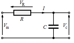
Suppose that initially Vin = 0 and the capacitor is discharged. Vc, therefore, is also zero. When a non-zero voltage Vin is applied, the voltage across the capacitor increases according to the following law:

Where T = RC.
Suppose now that instead of a condenser, we have a regular metal plate, or a strip of foil. According to the laws of physics, it also has a certain, albeit very small, capacity of the order of a few picofarads. It is easy to calculate that the time for which such a plate will be charged with a resistor of 1 MOM is 10 ^ 6 * 10 ^ (- 12) = 10 ^ (- 6) c. A very small value, however, for a microcontroller operating at a frequency of 10 MHz, will have time to pass as many as 10 clock cycles.
Now imagine that the plates touched man. Its capacity is two orders of magnitude higher than the capacity of the plate and is about 100-200 picofarads. Consequently, the time during which the plate is charged will increase significantly.
Below is the model of the sensor in the Proteus system.
Capacitor C1 acts as the own capacitance of our sensor plate, C2 together with the switch SW1 is the capacity of the touching person.
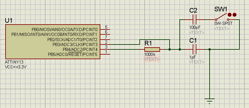
As we can see, the circuit is extremely simple and uses only two pins of the microcontroller. Moreover, if necessary, you can build a sensor on one pin, alternately switching it from output to input, but in this case I decided not to save the legs of the microcircuit.
The sensor polling algorithm is also very simple and follows from the above:
1) PB.4 we set to the output, and feed there 0. This will discharge the sensor.
2) PB.3 is set to the input by disabling the tightening (this is important! Pulling up the power supply will keep the sensor charged at all times, but we don’t need it).
3) We adjust the timer of the microcontroller to the frequency we need. The frequency is selected according to the following criterion: it must be large enough to capture the charge time and distinguish the “empty” sensor from the active, but at the same time small enough so that the timer does not overflow with the active sensor. Since in our device the microcontroller will work from the built-in clock generator to save space, its maximum frequency will be equal to 9.6 MHz, which is quite suitable according to the above criteria. Therefore, the timer will run without a prescaler, at the frequency of the microcontroller.
4) Turn on the timer
5) We display a logical unit in PB.4, thereby starting the process of charging tanks
6) Check the value on PB.3 until the log appears there. one.
7) Stop the timer.
8) Display in PB.4 log. 0 to discharge the sensor.
The resulting timer value is the number by which we will determine whether the sensor is empty or not. But comparing it directly with an approximate value is wrong. This will make the circuit very dependent on environmental conditions. For the sensor to work correctly, it is necessary to perform a calibration at startup, that is, to perform the described algorithm, and write the received timer value into an internal variable, SensorLow, considering it to be the value corresponding to the inactive sensor.
In the process of polling the sensor, it will be necessary to perform all the steps described, and compare the obtained value, say, with SensorLow + N, where N is the sensitivity threshold of our sensor.
Regarding the brightness control of the LED, this is easily achieved with the help of PWM (pulse-width modulation), in which instead of a constant voltage level the load is applied to rectangular pulses with an adjustable duty cycle. As a result, the average voltage value equals the logic level value multiplied by the duty cycle value. This technique is widely known, so I will not dwell on its detailed description.
A few words about the choice of LED and power source.
From the battery we need a long service life "on the shelf" (with low consumption), supply voltage 3-5 volts, for powering the controller and the LED, and a relatively high current with a fully lit LED - 10-15 mA.
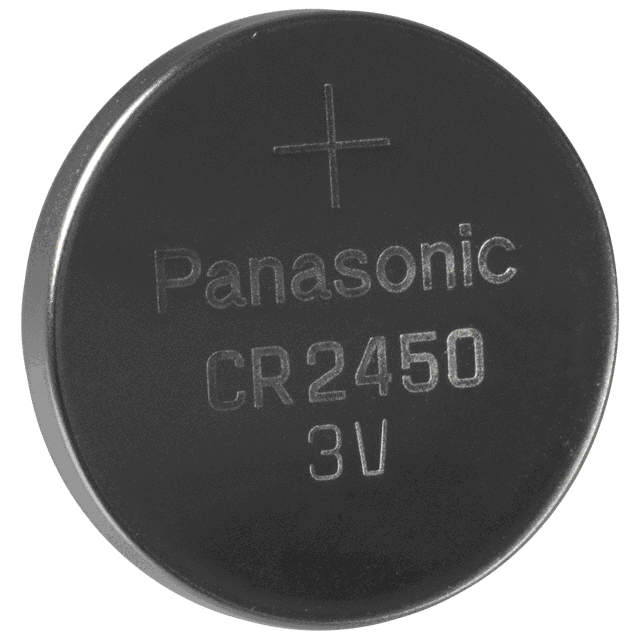
A lithium CR2450 battery with a voltage of 3.0 volts, with a capacity of approximately 610 mAh, capable of delivering large (up to 30 mA) currents and stored up to 10 years is ideal for these purposes.
The cost of such a battery is about 100 rubles.
The LED I chose blue, the color of the crystal, with a lens size of 5 mm, but everything is in your hands, you can experiment with different colors and shades. The main condition for the LED - the battery voltage should be enough to open it.
The voltage drop on my blue LED is about 2.7 volts, which means that when the battery is “slackened” by only 0.3 volts, the diode will not light up. There are LEDs with an even higher voltage drop, for such a lithium battery is no longer suitable.
However, a blessing in disguise - the high voltage drop across my LED made it possible to connect it without an additional resistor. As a result, the complete electrical circuit looks like this:
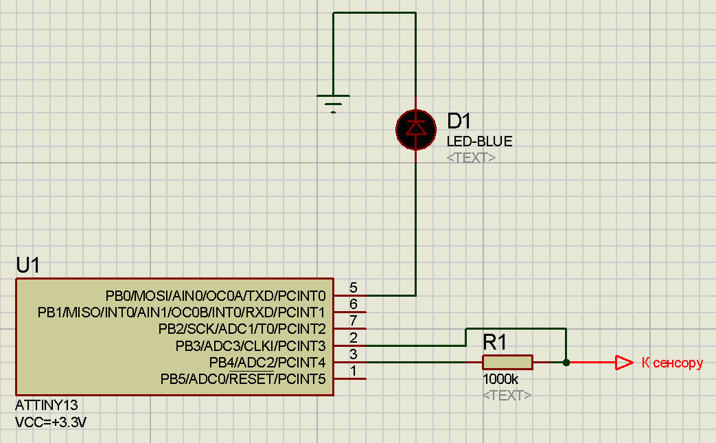
Extremely simple - a small 8-pin microcontroller ATTiny13, one mega-ohm resistor, one LED and a strip of foil as a sensor, which I pasted on the outer side of the plastic stand and connected to the circuit with a thin wire. Power pins and controller lands are not indicated on the diagram.
We are almost there, it remains to write the firmware, which the next step is devoted to (in the next article).
Part 1
Part 3
Step 2: create the construction
The long and dreary part is over, now everything will go faster. After I received my crystal, I wondered “where can I get a suitable glass cylinder in which the crystal can be concluded?” The answer was found in the store “everything for the home”, in the form of an excellent cylindrical stack for vodka costing 20 rubles per piece.
')
She attracted me for two reasons: firstly, she was without patterns, engravings and the correct form - an even glass cylinder. Secondly, it was rather thick-walled, which has a good effect on the strength of the structure.
The final construction to which we must come is shown below.
In principle, if you have grown a fist-sized crystal, or you simply do not like such stacks, you can choose any suitable transparent container. The main thing is to be able to seal it in consequence to prevent the weathering of the crystal.
Now our task is to find a plastic insert hollow inside, on which a crystal can be placed, and inside it a control circuit with a battery. I stopped at a plastic rosin box, which ideally entered the glass.
In the center of it we make a hole under the LED (in more detail on the choice of the LED I will focus on the part devoted to electronics), insert it there and seal it from the inside with a hot-melt gun. On the same glue, we plant a crystal outside a plastic stand, directly above the LED.
Making sure that everything is exactly as it should be, we proceed to the final stage of this step - we lubricate the outer surface of the stand with a sealant of a suitable color (I chose the black stand, respectively, and the black sealant) and insert it inside the glass. After the sealant hardens, you will have a completely sealed glass with a crystal inside, which can be highlighted by supplying power to the LED terminals.
I did not fill the crystal with anything, having stopped at the variant with a varnish and a hermetic vessel, but if you really want to be sure that the crystal will be stored for centuries, you can pour it with some kind of transparent organic composition (oil, for example). True, this will require you to properly seal, so that the device does not suddenly begin to leak.
We turn to the most interesting step - the development of electronics.
Step 3: develop electronics
After performing the above steps, we should have got a blank, to which, in principle, you can add a battery and a switch, and get the finished product. But such a souvenir will not stand out among the heaps of various "little things", sold for 50 rubles a bucket. Our goal at this step is to develop the electrical circuit of the device, which will firstly fit into our stand, secondly, it will not consume much current in idle mode (you can, of course, bring the switch out, but for me this really spoils the impression), and thirdly, it will provide what we wanted from the very beginning: a smooth increase in the glow of the crystal, when it is taken in hand, and the extinction after it is put in place.
In fact, we face two tasks:
1) Determine the touch to the device person
2) Control the brightness of the LED.
An excellent solution to the first task is the implementation of a capacitive sensor. Despite the sonorous name, it is very simple and requires, in fact, only the sensor itself (in the form of a simple piece of foil, wire, or pad on a printed circuit board), 1-2 pins of a microcontroller and a resistor with resistance from mega-ohms and above.
Let's turn to the theory. Suppose we have a series connection of a resistor and a capacitor, described in the wikipedia article "RC-circuit"
Suppose that initially Vin = 0 and the capacitor is discharged. Vc, therefore, is also zero. When a non-zero voltage Vin is applied, the voltage across the capacitor increases according to the following law:
Where T = RC.
Suppose now that instead of a condenser, we have a regular metal plate, or a strip of foil. According to the laws of physics, it also has a certain, albeit very small, capacity of the order of a few picofarads. It is easy to calculate that the time for which such a plate will be charged with a resistor of 1 MOM is 10 ^ 6 * 10 ^ (- 12) = 10 ^ (- 6) c. A very small value, however, for a microcontroller operating at a frequency of 10 MHz, will have time to pass as many as 10 clock cycles.
Now imagine that the plates touched man. Its capacity is two orders of magnitude higher than the capacity of the plate and is about 100-200 picofarads. Consequently, the time during which the plate is charged will increase significantly.
Below is the model of the sensor in the Proteus system.
Capacitor C1 acts as the own capacitance of our sensor plate, C2 together with the switch SW1 is the capacity of the touching person.
As we can see, the circuit is extremely simple and uses only two pins of the microcontroller. Moreover, if necessary, you can build a sensor on one pin, alternately switching it from output to input, but in this case I decided not to save the legs of the microcircuit.
The sensor polling algorithm is also very simple and follows from the above:
1) PB.4 we set to the output, and feed there 0. This will discharge the sensor.
2) PB.3 is set to the input by disabling the tightening (this is important! Pulling up the power supply will keep the sensor charged at all times, but we don’t need it).
3) We adjust the timer of the microcontroller to the frequency we need. The frequency is selected according to the following criterion: it must be large enough to capture the charge time and distinguish the “empty” sensor from the active, but at the same time small enough so that the timer does not overflow with the active sensor. Since in our device the microcontroller will work from the built-in clock generator to save space, its maximum frequency will be equal to 9.6 MHz, which is quite suitable according to the above criteria. Therefore, the timer will run without a prescaler, at the frequency of the microcontroller.
4) Turn on the timer
5) We display a logical unit in PB.4, thereby starting the process of charging tanks
6) Check the value on PB.3 until the log appears there. one.
7) Stop the timer.
8) Display in PB.4 log. 0 to discharge the sensor.
The resulting timer value is the number by which we will determine whether the sensor is empty or not. But comparing it directly with an approximate value is wrong. This will make the circuit very dependent on environmental conditions. For the sensor to work correctly, it is necessary to perform a calibration at startup, that is, to perform the described algorithm, and write the received timer value into an internal variable, SensorLow, considering it to be the value corresponding to the inactive sensor.
In the process of polling the sensor, it will be necessary to perform all the steps described, and compare the obtained value, say, with SensorLow + N, where N is the sensitivity threshold of our sensor.
Regarding the brightness control of the LED, this is easily achieved with the help of PWM (pulse-width modulation), in which instead of a constant voltage level the load is applied to rectangular pulses with an adjustable duty cycle. As a result, the average voltage value equals the logic level value multiplied by the duty cycle value. This technique is widely known, so I will not dwell on its detailed description.
A few words about the choice of LED and power source.
From the battery we need a long service life "on the shelf" (with low consumption), supply voltage 3-5 volts, for powering the controller and the LED, and a relatively high current with a fully lit LED - 10-15 mA.
A lithium CR2450 battery with a voltage of 3.0 volts, with a capacity of approximately 610 mAh, capable of delivering large (up to 30 mA) currents and stored up to 10 years is ideal for these purposes.
The cost of such a battery is about 100 rubles.
The LED I chose blue, the color of the crystal, with a lens size of 5 mm, but everything is in your hands, you can experiment with different colors and shades. The main condition for the LED - the battery voltage should be enough to open it.
The voltage drop on my blue LED is about 2.7 volts, which means that when the battery is “slackened” by only 0.3 volts, the diode will not light up. There are LEDs with an even higher voltage drop, for such a lithium battery is no longer suitable.
However, a blessing in disguise - the high voltage drop across my LED made it possible to connect it without an additional resistor. As a result, the complete electrical circuit looks like this:
Extremely simple - a small 8-pin microcontroller ATTiny13, one mega-ohm resistor, one LED and a strip of foil as a sensor, which I pasted on the outer side of the plastic stand and connected to the circuit with a thin wire. Power pins and controller lands are not indicated on the diagram.
We are almost there, it remains to write the firmware, which the next step is devoted to (in the next article).
Part 1
Part 3
Source: https://habr.com/ru/post/111627/
All Articles