Designing power subsystem electronic meter
annotation
The article presents a structural analysis of the power subsystem of stationary measuring instruments for electric energy quality indicators (SI PKE).
This principle is also suitable for the design of the power supply subsystem of other various devices and electronic devices.
Introduction
Under the stationary SI PKE are understood devices - gauges, designed to conduct monitoring or long-term audit of electrical networks. In both cases, the meters are installed near the control points for a long time (1 ... 3 or more months) and are under the constant control of the operators. As a rule, control is carried out remotely, data is transmitted to the dispatch computer via wired or wireless interfaces. In the case when it is necessary to maintain several control points, the meters are combined into information networks. Such networks that collect and computerize data (information) are commonly called measuring systems (SI).
Power for such spatially distributed meters is provided from uninterruptible power supplies (UPS), which can be autonomous and located near the meter, or can be organized as a single (centralized) source, which is located in the control room.
The second power option can be implemented using wired interfaces such as RS485, CAN, Ethernet ...
The use of autonomous UPSs increases the overall reliability of the system, but is more expensive. In some cases, it is possible to implement compromise power options - with the use of group UPSs, when several meters are powered from each of the placed sources.
Figure 1 shows the symbol of a typical UPS for system use. The UPS is a three-phase AC / DC converter with stabilizing functions. It has a galvanic barrier, the output is protected from short circuit. The UPS retains its functions when there is at least one of the phase voltages that has fallen no more than to the established limits. In order to further improve the reliability of the UPS system, it is useful to provide a service interface (RS485, RS232, CAN) for operational communication with the control computer. This will allow the dispatcher to change the UPS operation modes, receive pre-emergency information (overheating, etc.), etc.

Fig. 1. Symbol of power source for system use
2. Selection of components of the power subsystem SI PKE
In [1] shows a typical structural diagram of SI PKE. A feature of the circuit is the presence of up to five galvanic power zones. Within each zone, there is a voltage (or several voltages) that do not have a galvanic connection - they say that the zones are separated by galvanic barriers so that the common wire in each zone is different. Thus, when designing a power subsystem for SI PKE, it is necessary to form several power groups — one for each zone.
Figure 2 shows a typical block diagram of the power subsystem. Notation used: input and output converter - input converter, VTP - secondary converter, LDO - linear regulator with a small voltage drop “input-output”.
The structure has four galvanic zones. Voltages belonging to the same zone have a distinctive designation, for example, voltages of zone No. 4 are designated: U1.4, U2.4, U3.4, U4.4.
The structure contains the most complete set of transducers, taking into account the presence of galvanic barriers, which form four so-called. galvanic zones. Zone 1 - zone of input power supply voltage, zone 2 - zone of the main electronic circuit, zone 3 - zone of interface signals, zone 4 - zone of input measuring circuits (converters).
The structure may vary depending on the purpose of the projected SI PKE. In particular, simple portable meters can have only one galvanic zone. The most sophisticated meters can have several galvanic zones for input measuring circuits.
')

Fig. 2. Typical structure of power subsystem SI PKE
2.1. Examples of structural implementations of the power subsystem
Consider the examples of the structural implementation of the power subsystem with the primary source of direct current and the source of alternating current.
DC power structures.
In fig. 3 shows the structure of the power supply from the primary source with an unstable output voltage (U1.1).
We read the scheme in accordance with the legend.
The input transducer (G1) of the reduction type has a galvanic barrier between the input voltage and the converted U1.2. Properties of the input converter: - the converter has stabilizing functions (the ++ sign) and allows the supply of voltage in a wide range (sign 2: 1), for example, (36 ... 72) V; -output has protection against short circuit (sign x at the output).
An LDO converter (G3) is installed at the G1 output to reduce the noise components of U1.2. Typically, this improvement in supply voltage requires analogue measuring circuits. Less sensitive to noise digital circuits can be powered directly by the voltage U1.2, which - and this should always be taken into account, is somewhat higher than the stabilized U2.2.
The second load for U1.2 is the G2 converter. It is designed to power the external interface driver. The converter has a galvanic barrier and its output is unstabilized.
For simplicity, galvanic zone 4 (Fig. 2) is not shown.
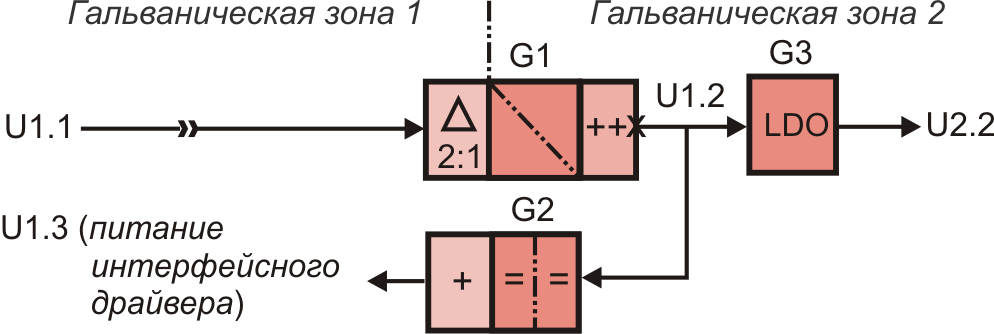
Fig. 3. Power supply structure from a source of unstabilized voltage. Interface driver converter has galvanic barrier
The scheme presented in fig. 4 has the same purpose and differs in the implementation of power for the interface driver. A step-down converter with stabilizing functions was used to power the interface driver, but, unlike G2, it does not have a galvanic barrier.
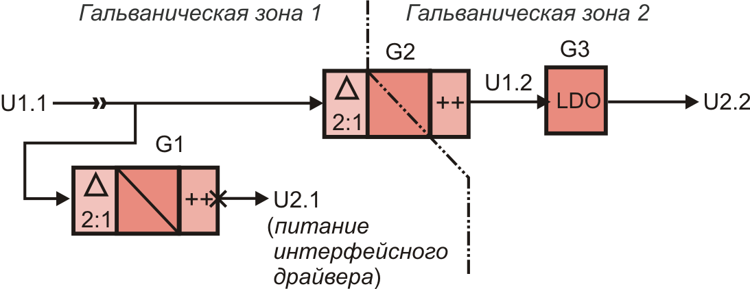
Fig. 4. Structure of power supply from a source of unstabilized voltage.
Interface driver converter does not have a galvanic barrier
Let's compare. The first scheme (Fig. 3) is built on a more reliable (tested) structure. It has a relatively expensive converter (module) with UGR. The second scheme (Fig. 4) is more attractive, since uses an interface power converter without UGR (microcircuit) - apparently cheap. It is not tested and involves the use of a converter with a wide input range.
Structures with AC power.
In a number of operational situations, it is possible to power the SI PKE from a special redundant network of DC or AC power with high, as a rule, voltage. The block diagram of the power subsystem in this case can have an AC-to-DC converter as an input power converter. Often, such converters allow you to apply a constant voltage to the input. In fig. 5 shows the structure of the power supply from a redundant power supply. A rectifier is installed at the input of the converter, then the voltage is applied to the input of the down-converter with an electroplated barrier.
It should be borne in mind that the same circuit in some cases allows to supply power from the measured phase voltage. For this, the input voltage range of the converter should be wide enough so that the power of the meters is not interrupted while the input voltage is in its current state (interesting for the study).
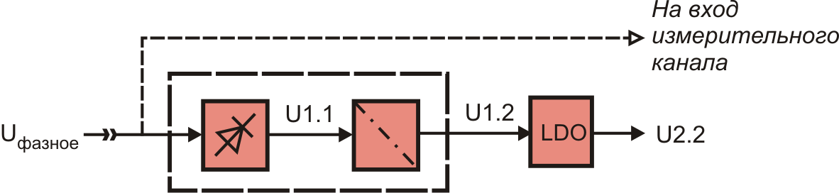
Fig. 5. Power supply structure from redundant alternating current network
2.2. Manufacturers of power components.
There are a dozen or three or four manufacturers on the nutrition components market. The most well represented are the following firms.
Conversion module manufacturers: Aimtec, Recom, PEAK, Traco, Rohm, Mean Weel, Murata PS, Chinfa Electronics, Fabrimex, XP, Mornsun, Irbis, etc. [2-5]
Conversion chip manufacturers: Analog Devices, Texas Instruments, Linear Technology, Microchip, Maxim, Exar, On Semiconductor, etc. [6-10]
Source: https://habr.com/ru/post/111358/
All Articles