Anti-interference coding using various codes
This is a continuation of the article on noise-tolerant coding, which has been in draft for a very long time. In the last part there is nothing interesting from a practical point of view - only general information about why this is needed, where it is used, etc. In this part some (most simple) codes will be considered for detecting and / or correcting errors. So let's go.
I tried to describe everything as easily as possible for a person who has never worked on coding information, and without any special mathematical formulas.
When we transmit a message from the source to the receiver, an error may occur during data transmission (interference, equipment malfunction, etc.). In order to detect and correct the error, error-correcting coding is applied, i.e. encode the message so that the receiving party knows whether an error has occurred or not, and if it could correct the errors in case of their occurrence.
In essence, coding is the addition to the source information of additional, verification, information. For encoding, a coder is used on the transmitting side, and a decoder is used on the receiving side to receive the original message.
Code redundancy is the amount of verification information in a message. It is calculated by the formula:
')
Parity checking is a very simple method for detecting errors in a transmitted data packet. With this code, we can not recover data, but we can detect only a single error.
Each data packet has one parity bit , or the so-called parity bit . This bit is set during the writing (or sending) of the data, and then calculated and compared during the reading (receiving) of the data. It is equal to the sum modulo 2 of all data bits in the packet. That is, the number of units in the package will always be even . Changing this bit (for example, from 0 to 1) reports an error that has occurred.
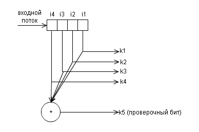
Below is the block diagram of the encoder for this code.
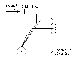
and and decoder
Example:
As mentioned earlier, this method serves only to determine a single error. In the case of a change in the state of two bits, it is possible that the calculation of the check bit coincides with the recorded one. In this case, the system will not detect the error, and this is not good. For example:
Since about 90% of all irregular errors occur with just a single bit, parity checking is enough for most situations.
As mentioned in the previous part, Richard Hamming did a lot for noise-tolerant coding. In particular, he developed a code that provides detection and correction of single errors with the minimum possible number of additional check bits. For each number of check characters, a special marking of the form (k, i) is used, where k is the number of characters in the message, i is the number of information characters in the message. For example, there are codes (7, 4), (15, 11), (31, 26). Each check character in a Hamming code represents a sum modulo 2 of some subsequence of data. Let us consider at once with an example, when the number of information bits i in a block is 4 - this is a code (7.4), the number of check symbols is 3. Classically, these symbols are placed in positions equal to powers of two in ascending order:
but it is possible to place them at the end of the transmitted data block (but then the formula for calculating them will be different).
Now let's calculate these check characters:
So, in the coded message we get the following:
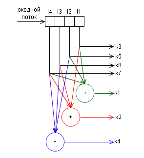
In principle, the operation of this algorithm is discussed in great detail in the article Hamming Code. An example of how the algorithm works , so I don’t see any point in describing in detail this article. Instead, I will give the block diagram of the encoder:
and decoder
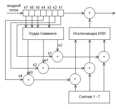
(maybe quite confusing, but it’s better not to draw)
e0, e1, e2 are defined as functions depending on the bits k1 - k7 received by the decoder:
The set of these values of e2e1e0 is a binary record of the position where an error occurred during data transfer. The decoder calculates these values, and if all of them are not equal to 0 (that is, 000 does not work), then corrects the error.
In the communication channel, apart from single errors caused by noise, there are often packet errors caused by impulse noise, fading, or fallout (during digital video recording). At the same time, hundreds or even thousands of bits of information appear to be amazed. It is clear that no interfering code will be able to cope with such an error. To be able to deal with such errors, codes-products are used. The principle of operation of such a code is shown in the figure:
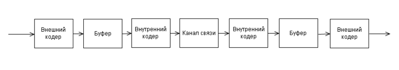
The transmitted information is encoded twice: in the external and internal coders. A buffer is set between them, whose operation is shown in the figure:
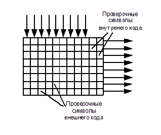
Informational words pass through the first noise-tolerant coder, called external, because he and the corresponding decoder are located on the edges of the noise-immune coding system. Here, the check characters are added to them, and they, in turn, are buffered by columns, and displayed line by line. This process is called mixing or interleaving .
When lines are output from the buffer, the check characters of the internal code are added to them. In this order, information is transmitted over a communication channel or recorded somewhere. Let us agree that both the internal and external codes are Hamming codes with three verification symbols, that is, both can be corrected by one error in the code word (the number of “cubes” in the figure is not critical - it is just a diagram). At the receiving end there is exactly the same memory array (buffer) in which information is entered line by line, and displayed in columns. If a packet error occurs (crosses in the figure in the third and fourth lines), it is distributed in small portions in the code words of the external code and can be corrected.
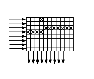
The purpose of the external code is clear - fix batch errors. Why do we need an internal code? The figure, except for the batch, shows a single error (fourth column, top row). There are two errors in the code word located in the fourth column, and they cannot be corrected, because external code is designed to correct one error. To get out of this situation, you just need an internal code that corrects this single error. The received data first passes the internal decoder, where single errors are corrected, then they are written to the buffer line by line, output in columns and fed to an external decoder, where the packet error occurs.
The use of product codes increases the power of the error-correcting code many times with the addition of insignificant redundancy.
PS: I was engaged in this topic 3 years ago, when I wrote my graduation project, I might have missed something. All corrections, comments, suggestions - please through private messages
I tried to describe everything as easily as possible for a person who has never worked on coding information, and without any special mathematical formulas.
When we transmit a message from the source to the receiver, an error may occur during data transmission (interference, equipment malfunction, etc.). In order to detect and correct the error, error-correcting coding is applied, i.e. encode the message so that the receiving party knows whether an error has occurred or not, and if it could correct the errors in case of their occurrence.
In essence, coding is the addition to the source information of additional, verification, information. For encoding, a coder is used on the transmitting side, and a decoder is used on the receiving side to receive the original message.
Code redundancy is the amount of verification information in a message. It is calculated by the formula:
k / (i + k) whereFor example, we transfer 3 bits and add 1 check bit to them - the redundancy is 1 / (3 + 1) = 1/4 (25%).
k is the number of check bits,
i is the number of information bits.
')
Parity code
Parity checking is a very simple method for detecting errors in a transmitted data packet. With this code, we can not recover data, but we can detect only a single error.
Each data packet has one parity bit , or the so-called parity bit . This bit is set during the writing (or sending) of the data, and then calculated and compared during the reading (receiving) of the data. It is equal to the sum modulo 2 of all data bits in the packet. That is, the number of units in the package will always be even . Changing this bit (for example, from 0 to 1) reports an error that has occurred.
Below is the block diagram of the encoder for this code.
and and decoder
Example:
Initial data: 1111
Data after coding: 1111 0 (1 + 1 + 1 + 1 = 0 (mod 2))
Received data: 1 0 110 (second bit changed)
As we see, the number of units in the received packet is odd, therefore, an error occurred during transmission.
As mentioned earlier, this method serves only to determine a single error. In the case of a change in the state of two bits, it is possible that the calculation of the check bit coincides with the recorded one. In this case, the system will not detect the error, and this is not good. For example:
Initial data: 1111
Data after coding: 1111 0 (1 + 1 + 1 + 1 = 0 (mod 2))
Received data: 1 00 10 (2 and 3 bits changed)
In the received data, the number of units is even, and therefore the decoder will not detect an error.
Since about 90% of all irregular errors occur with just a single bit, parity checking is enough for most situations.
Hamming code
As mentioned in the previous part, Richard Hamming did a lot for noise-tolerant coding. In particular, he developed a code that provides detection and correction of single errors with the minimum possible number of additional check bits. For each number of check characters, a special marking of the form (k, i) is used, where k is the number of characters in the message, i is the number of information characters in the message. For example, there are codes (7, 4), (15, 11), (31, 26). Each check character in a Hamming code represents a sum modulo 2 of some subsequence of data. Let us consider at once with an example, when the number of information bits i in a block is 4 - this is a code (7.4), the number of check symbols is 3. Classically, these symbols are placed in positions equal to powers of two in ascending order:
first check bit at 2 0 = 1;
the second check bit for 2 1 = 2;
the third check bit is 2 2 = 4;
but it is possible to place them at the end of the transmitted data block (but then the formula for calculating them will be different).
Now let's calculate these check characters:
r1 = i1 + i2 + i4
r2 = i1 + i3 + i4
r3 = i2 + i3 + i4
So, in the coded message we get the following:
r1 r2 i1 r3 i2 i3 i4
In principle, the operation of this algorithm is discussed in great detail in the article Hamming Code. An example of how the algorithm works , so I don’t see any point in describing in detail this article. Instead, I will give the block diagram of the encoder:
and decoder
(maybe quite confusing, but it’s better not to draw)
e0, e1, e2 are defined as functions depending on the bits k1 - k7 received by the decoder:
e0 = k1 + k3 + k5 + k7 mod 2
e1 = k2 + k3 + k6 + k7 mod 2
e2 = k4 + k5 + k6 + k7 mod 2
The set of these values of e2e1e0 is a binary record of the position where an error occurred during data transfer. The decoder calculates these values, and if all of them are not equal to 0 (that is, 000 does not work), then corrects the error.
Work codes
In the communication channel, apart from single errors caused by noise, there are often packet errors caused by impulse noise, fading, or fallout (during digital video recording). At the same time, hundreds or even thousands of bits of information appear to be amazed. It is clear that no interfering code will be able to cope with such an error. To be able to deal with such errors, codes-products are used. The principle of operation of such a code is shown in the figure:
The transmitted information is encoded twice: in the external and internal coders. A buffer is set between them, whose operation is shown in the figure:
Informational words pass through the first noise-tolerant coder, called external, because he and the corresponding decoder are located on the edges of the noise-immune coding system. Here, the check characters are added to them, and they, in turn, are buffered by columns, and displayed line by line. This process is called mixing or interleaving .
When lines are output from the buffer, the check characters of the internal code are added to them. In this order, information is transmitted over a communication channel or recorded somewhere. Let us agree that both the internal and external codes are Hamming codes with three verification symbols, that is, both can be corrected by one error in the code word (the number of “cubes” in the figure is not critical - it is just a diagram). At the receiving end there is exactly the same memory array (buffer) in which information is entered line by line, and displayed in columns. If a packet error occurs (crosses in the figure in the third and fourth lines), it is distributed in small portions in the code words of the external code and can be corrected.
The purpose of the external code is clear - fix batch errors. Why do we need an internal code? The figure, except for the batch, shows a single error (fourth column, top row). There are two errors in the code word located in the fourth column, and they cannot be corrected, because external code is designed to correct one error. To get out of this situation, you just need an internal code that corrects this single error. The received data first passes the internal decoder, where single errors are corrected, then they are written to the buffer line by line, output in columns and fed to an external decoder, where the packet error occurs.
The use of product codes increases the power of the error-correcting code many times with the addition of insignificant redundancy.
PS: I was engaged in this topic 3 years ago, when I wrote my graduation project, I might have missed something. All corrections, comments, suggestions - please through private messages
Source: https://habr.com/ru/post/111336/
All Articles