Lab DC power supply from power supply
A few weeks ago, for some experience, I needed a constant voltage source of 7V and a current of 5A. Then he went in search of the necessary BP in the back room, but this was not there. After a couple of minutes, I remembered that I had a computer power supply in my hands in the back room, but this is an ideal option! Shaking brains, I gathered together ideas and after 10 minutes the process began.
For the manufacture of a laboratory constant voltage source will need:
- power supply from computer
- terminal block
- Light-emitting diode
- resistor ~ 150 ohm
- toggle switch
- shrinking
- screeds
The power supply may be somewhere not needed. In the case of a target acquisition - from $ 10. I have not seen cheaper. The rest of the items on this list are cheap and not in short supply.
From the tools you will need:
- glue gun aka hot glue (for mounting the LED)
- soldering iron and related materials (tin, flux ...)
- drill
- drill with a diameter of 5mm
- screwdrivers
- side cutters (nippers)
')
Manufacturing
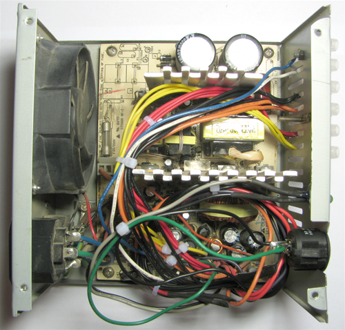
So, the first thing I did was check the performance of this power supply unit. The device turned out to be serviceable. You can immediately cut off the plug, leaving 10-15 cm on the side of the plug, because You may need it. It is worth noting that you need to calculate the length of the wire inside the power supply unit so that it is enough to reach the terminals without tension, but also so that it does not occupy all the free space inside the power supply unit.
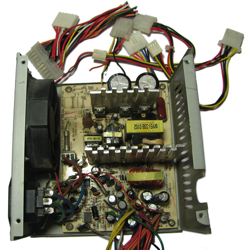
Now you need to separate all the wires. To identify them, you can look at the board, and more precisely at the sites to which they go. Sites must be signed. In general, there is a generally accepted color marking scheme, but the manufacturer of your PSU may have colored the wires differently. To avoid "misunderstandings" it is better to independently identify the wires.
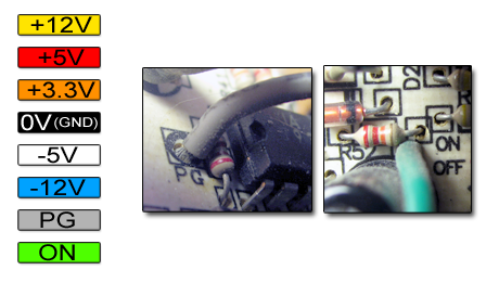
Here is my "wired gamma." She, if I'm not mistaken, is the standard.
From yellow to blue, I think, clearly. What do the two lower colors mean?
PG (abbr. From " power good ") is the wire that we use to install the LED indicator. Voltage - 5V.
ON - wire that must be closed with GND to turn on the power supply.
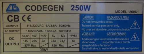
The power supply has wires that I did not describe here. For example, purple + 5VSB. We will not use this wire, since the current limit for it is 1A.
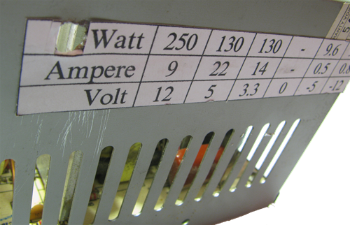
While the wires do not bother us, you need to drill a hole for the LED and make a sticker with the necessary information. The information itself can be found on the factory label, which is located on one of the sides of the PSU. When drilling you need to take care that the metal chips do not get inside the device, because This can lead to extremely negative consequences.
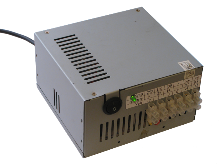
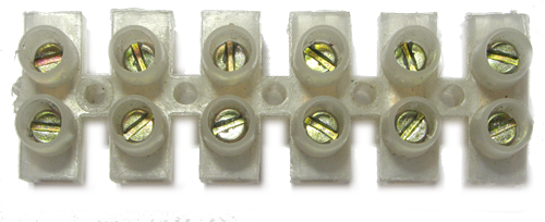
I decided to install a terminal block on the front of the power supply unit. At home there was a 6-terminal block that suited me.
I was lucky, because The slots in the power supply and the holes for mounting the pads coincided, and even the diameter came up. Otherwise, it is necessary to either drill out the PS slots, or drill new holes in the PSU.
The pad is installed, now you can remove the wires, remove insulation, twist and tin. I output 3-4 wires of each color, except white (-5V) and blue (-12V), because them in BP one at a time.
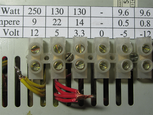
The first one is the next one.
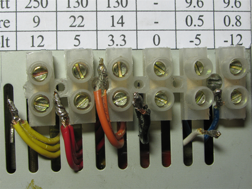
All wires are tinned. Can be clamped in the terminal.
Install LED
I took the
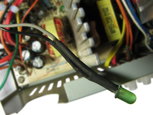
It turns out this thing. True, I overheated a little heat shrink, but it's not scary.
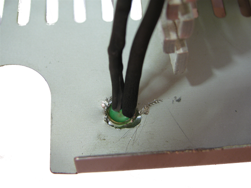
Now install the LED in the hole, which I drilled at the very beginning.
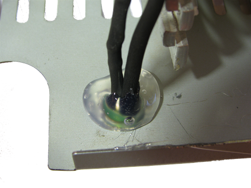
Pour hot glue. If not, then you can replace the super-glue.
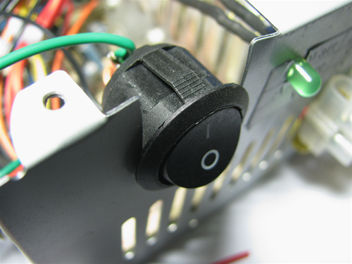
Power supply switch
I decided to install the switch to the place where before the power supply unit had wires coming out.
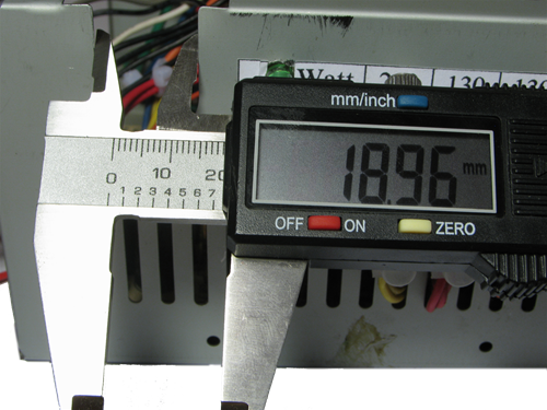
Measured the diameter of the hole and ran to look for a suitable toggle switch.
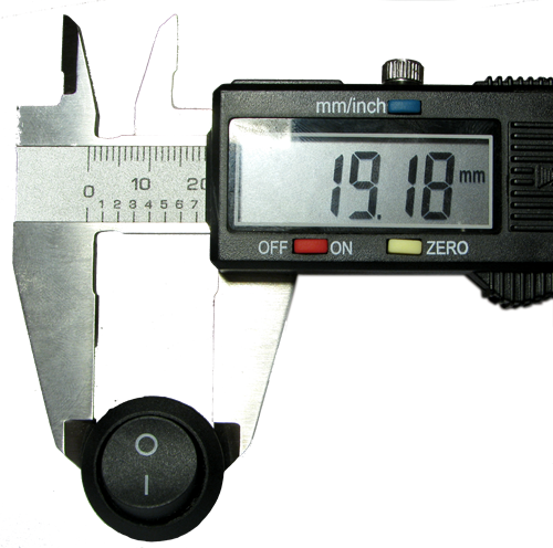
I rummaged a bit and found the perfect switch. Due to the difference in 0,22mm, he perfectly fell into place. Now it is left to solder ON and GND to the tumbler, then install it into the case.
The main work is done. It remains to bring marafet.
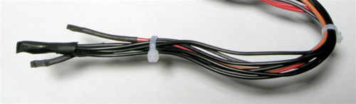
Tails of wires that are not used must be insulated. I made it shrink. Wires of the same color are better insulated together.
All laces neatly placed inside.
We fasten the lid, turn on, bingo!
This power supply can get a lot of different voltages, using the potential difference. Please note that this technique does not roll for some devices.
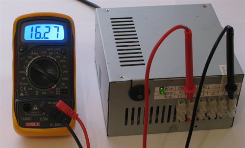
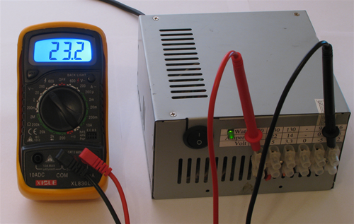
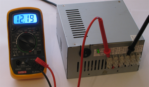
Here is the range of voltages that can be obtained.
The first parenthesis is positive, the second - negative.
24.0V — (12V -12V)
17.0V — (12V -5V)
15.3V — (3.3V -12V)
12.0V — (12V 0V)
10.0V — (5V -5V)
8.7V — (12V 3.3V)
8.3V — (3.3V -5V)
7.0V — (12V 5V)
5.0V — (5V 0V)
3.3V — (3.3V 0V)
1.7V — (5V 3.3V)
-1.7V — (3.3V 5V)
-3.3V — (0V 3.3V)
-5.0V — (0V 5V)
-7.0V — (5V 12V)
-8.7V — (3.3V 12V)
-8.3V — (-5V 3.3V)
-10.0V — (-5V 5V)
-12.0V — (0V 12V)
-15.3V — (-12V 3.3V)
-17.0V — (-12V 5V)
-24.0V — (-12V 12V)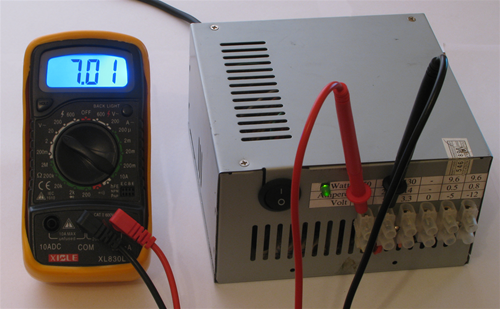
That's how we got a constant voltage source with short-circuit protection and other goodies.
Rationalization ideas:
- use self-locking pads, as suggested here , or use terminals with insulated lambs in order to miss the screwdriver once again.
Source: https://habr.com/ru/post/111246/
All Articles