VU meter from scratch

Introduction
I remember how, at ten years old, I took up the soldering iron for the first time, and by the age of four, I had already assembled a radio-controlled car by the age of four, but with the advent of the computer, I abandoned this noble occupation. And so, literally two weeks ago, I was visited by the idea of making something beautiful. Thought and decided to make VU - meter. I started digging forums on electronics, in search of the best, in my opinion, implementation of this device. After a day of searching, I came across an article in the magazine “ RadioHobby ”, having searched a little more, I found a printed circuit board pattern. So that neither the logic nor the printed circuit board belongs to me, I proposed this scheme, as it is written in the journal - Marcin Vyazan.
Here the fun begins ...
Traffic caution
This is a precision indicator of the sound signal level with an extended dynamic range and increased accuracy of induced levels. The audio signal is fed to a precision detector, made on the op amp U1, diodes D1, D2 and capacitor C6. The rectified and smoothed voltage from the detector output goes directly to the input of the IC of the driver of the LED line U2 and through the divider R4R5, attenuating the signal by 5 dB, to the similar driver U3. The outputs of both drivers are interlaced so that their like-named outputs in a common line of seventeen D3-D19 LEDs correspond to levels shifted by these 5 dB (the dB operation levels in the diagram ) are indicated to the right of the LEDs). Thus, the indication of signals from -23 dB to +5 dB in 1 dB steps for levels from -6 to +5 dB is provided. Together with the color marking (D19-D17 - red, D16, D15 - yellow, other green), such a construction of indicators provides a convenient observation of the signal level near the nominal. The device is powered from a 12V single-pole source. The integrated stabilizer U4 IC provides power to the LED array and through R6D20-D22 forms the reference voltage of the “artificial ground” for the OU U1 and the drivers U2, U3. The sensitivity of the device 0.775 V = 0 dB, the upper limit of the frequency range of 22 kHz
')
RadioHobby 1/2008, p. 23-24
In general, the article is aimed at an audience of readers with basic skills of working with a soldering iron and wanting to do something interesting, which has practical application and is not too difficult to implement. The article describes a bare test sample, in the future I plan to order plexiglas with dimensions of 15 * 150 * 100 mm, there will be 20 of them for each of the two channels, the blocks will be located horizontally. In each block there will be 3 diodes. It should be something like VU - TOWER.
Closer to the point
PCB manufacturing
First, we need to erase the PCB. To do this, we take some money and go to the radio market, or another place where you can buy:
- Steklotekstolit one-sided size 10 * 15 ( ~ 50r )
- Ferric chloride ( ~ 60r per 100g )
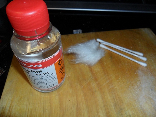
- Glycerin ( ~ 40r )
- Photo paper Lamond glossy 120 or 140 g / m ^ 2 ( ~ 200r per 50 sheets )
- Acetone
We will produce the PCB using the laser-iron method, or simply LUT. The technology is based on the fact that under high temperature the toner from the photo paper is fixed on the foil textolyte, creating a protective pattern that protects the copper under the print from iron chloride poisoning.
After we have stocked up with everything we need, we can start making the board.
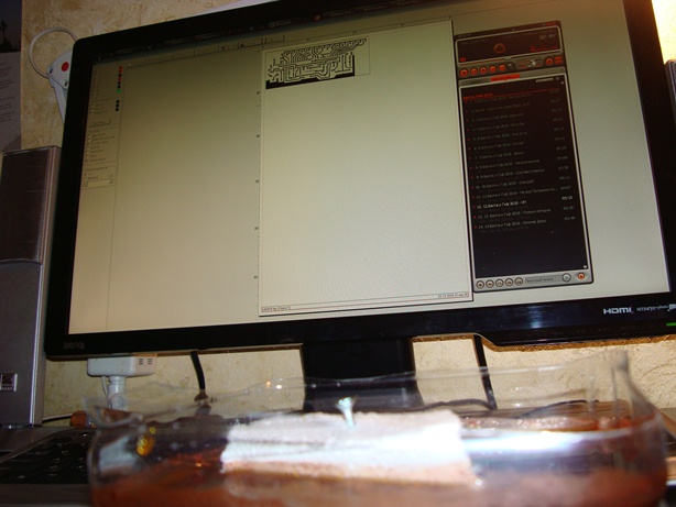
Download any program to open * .lay (I used Sprint Layout 5 ) and download the project board .
We print a board image on a laser printer, and it is desirable to specify high contrast and print quality in the printer driver settings. Also in Sprint Layout we remove the layer with captions, and set the color of the tracks to black. It is necessary to print in mirror image. It is advisable not to touch the paper with your fingers on the surface, so as not to leave greasy stains on it.


After printing, carefully cut it out and until it is put off.

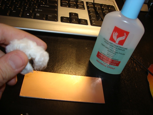
We take glass fiber laminate already cut to the required dimensions (115 * 45 mm), grind with fine sandpaper, and remove grease stains with acetone or nail polish remover.
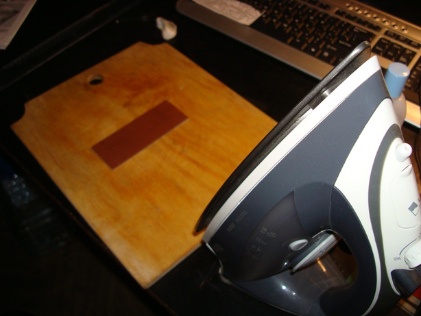
Next, we apply the print toner down to the glass fiber laminate and iron the iron very carefully at the maximum temperature. This is a very important point, it is necessary to iron every corner, every square millimeter of paper. We iron until paper slightly turns yellow. It took me about 5-7 minutes.

Let the board cool for 5 - 10 minutes and substitute it under the stream of water. Gently move your fingers to roll the paper until it is completely separated from the plate. At this stage it is important to check the quality of the print well, because if there are places where the toner does not print, they will wipe out and the contacts will be broken. If everything is bad, then repeat the process again, if there are small shoals, then gloss over them with a marker.


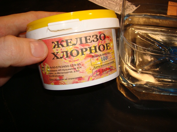
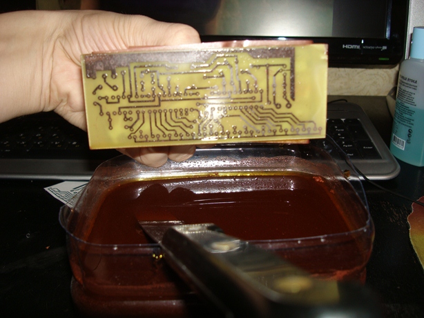
Next, prepare a solution of ferric chloride in water. Usually 100 g of powder is enough for 0.5 - 0.7 liters of water. We pour the powder into the water, and not vice versa, in small portions, since the reaction proceeds with the release of a large amount of heat. Mixing bring to a uniformly rusty color.
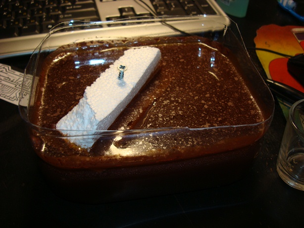
Gently at an angle, lower our board into the solution, hold for a while periodically checking how the process is going. On average, the etching process takes from 10 to 40 minutes.


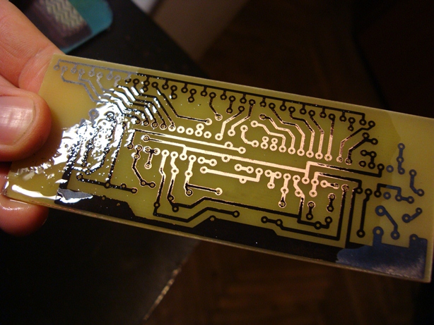
When all unnecessary copper is corroded, we take out the board and rinse it under running water. Next, carefully consider the fee for the presence of copper residues and gaps. If there are none, then everything turned out great and the PCB is almost ready. There are very few. Again, take the acetone and carefully remove the toner from the board.

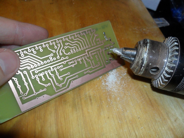
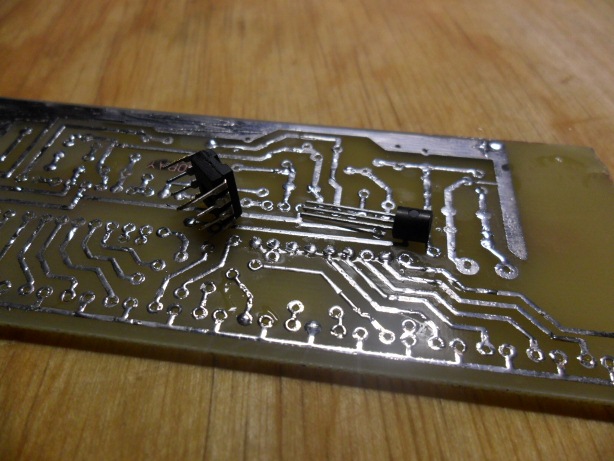
You can start to drill. Since I do not have drills, like other precision tools, I used a regular construction drill.

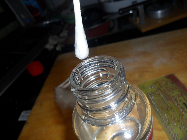
Next we need to tin the board. We put the soldering iron to warm up, but for now we take a cotton swab into the glycerin and put a layer on the board. When the soldering iron is heated, we take a bit of solder with a sting and pass through all the tracks of the board. It is better to cover all the tracks with tin to eliminate the oxidation of copper and to be sure that the contact is not broken anywhere. After that we wash the board from glycerin under running water and let it dry.


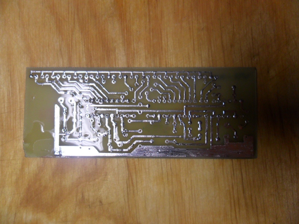
So the PCB is ready. Now you can start with filling it with electronic components.
Filling the board with stuffing
Shopping list
- IC LM3916N-1 PDIP18 * 2pcs (~ 100rub each)
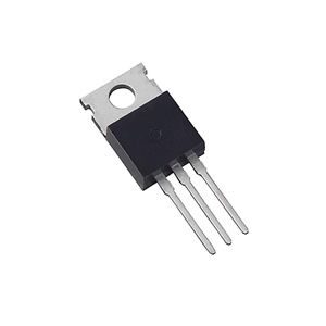
- Power conditioner 78L05 - 1pc (~ 20p) *
- Diodes 1N4148 (KD522A) 150mA, 100V DO-35 * 5pcs (~ 1p each)
- Operational amplifier TL081 PDIP8 - 1pc (~ 20p)
Capacitors:
- K10-17A H50 0.1mkF * 2pcs (~ 5p)
- K10-17A H90 0.33µF - 1pc (~ 5p)
- K50-35 47µF 16V * 3pcs (~ 5p)
- K50-35 470µF 16B - 1pc (~ 5p)
Resistors
- 330 ohm
- 2.2 kΩ
- 3.0 kΩ
- 3.9 kΩ
- 47 kΩ
- 120 kΩ
- Trimmer resistor to 10kΩ, I took 3362-1-103 (~ 20p)
I took S1-4 0.25 W came up perfectly, take each of 5 pieces, there will be unnecessary scared ones, it is better to have a prozapas than to go shopping for a component again because of a broken leg.
* About the voltage regulator. Initially I soldered the circuits to 78L05, after switching it on it was very hot, the stabilizer is rated for 100mA. The power consumption of the diodes turned out to be much higher, so I replaced it with the LM7805 in the TO220 package, which is already designed for 1A and fixed the radiator to it. So if the diodes are with great amperage, I advise you to take care of the stabilizer.
Also, if you wish, you can take care of the sockets for the microcircuits, for it is quite problematic to evaporate the microcircuits in the event of a malfunction.
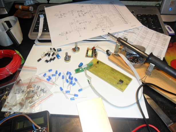
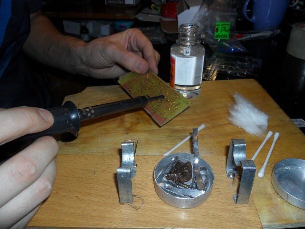
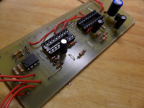
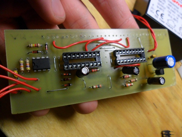
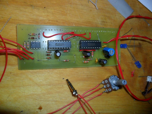
I think the process of soldering does not need an explanation, so I offer you just photos without comment.
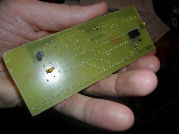


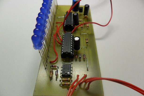
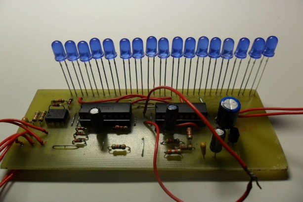
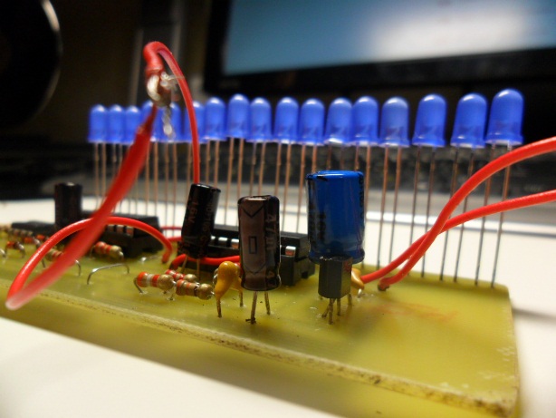

Demonstration of the working sample
And one more video, already two assembled drivers
Conclusion
In general, the assembly took about one evening, the price of the issue is about 600 rubles, taking into account the cost of the diodes. How to use this device depends on your imagination, I told you about my idea, I think this driver will fit in well with the company in the car and in any speaker system. In addition, this driver has 2 signal level display modes: BAR and DOT. To switch them, it is necessary to close or open the contacts indicated on the S1P / L printed circuit board. I especially liked the implementation of this device using plexiglass, when blocks of 10-20 mm thick are cut and a diode is inserted into each block. It looks very beautiful.
I would also like to add that this is part of one big project for assembling a home audio system which will include:
- External USB DAC
- Graphic equalizer for 10 * 2 bands
- Spectrum Analyzer 20 * 20
- Amplifier with timbre on encoders
- And much more, exclusively with your own hands.
Now I do PCB layout for a spectrum analyzer . Who will be interested, happy to share all the information collected on this topic.
Source: https://habr.com/ru/post/111219/
All Articles