Few conclusions? Use RESET
 Many developers of devices on microcontrollers at least once faced with a situation where the selected MK is suitable for all parameters (speed, memory, availability of necessary functions), except for the number of I / O ports. It is especially annoying when only one “leg” is missing and because of this it is necessary to choose the next chip model. It will take up more space on the board, consume more energy, and finally it will simply cost more.
To save the port, developers resort to incredible tricks. For example, on one forum I came across a way to manage a shift register on a single port (data and clock pulse) via an RC chain. Some of these methods lead to a decrease in the reliability of the device and the deterioration of its repeatability (depending on the parameters of a particular instance of the chip), so it is necessary to resort to them with caution, having analyzed all the pros and cons.
However, there is a way to find an “extra” port that is simple, stable, and can be applied in many cases. This is the use of RESET pin.
')
In fact, I know two whole ways.
The first is that the MC has a special flag (fuse) RSTDISBL, which, when programmed (set to “0”), turns the RESET pin into a regular I / O port that can be used along with others. This method is simple, but has one major drawback: after such a switch, the MK cannot be programmed using a low-voltage programmer, usually the most common type of device. If you suddenly want to sew a new program into the MC, you will need a programmer using 12V at the RESET pin. Since such programmers are less common (in fact, their dignity manifests itself only in such a situation with a switched RESET, otherwise they are no better than low-voltage ones), I consider this method not very suitable when developing (and not copying the finished) device.
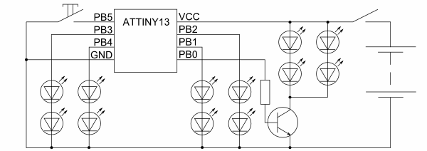
The second method was invented by me in the development of toys "Traffic Light". As planned, the traffic light had to signal in two directions (2 red, 2 green, 1 common yellow signal) and also wanted to be able to switch operating modes between normal and “night” (flashing yellow). Therefore, I needed 5 outputs for controlling the LEDs and one input for the mode switching button.
The smallest in the line of 8-bit AVR microcontrollers is Attiny13 and its modern counterparts ATtiny25, ATtiny45, Attiny85, which differ primarily in large memory. These devices are made in an 8-pin package, so if you subtract the leads for supplying power, a maximum of 6 I / O ports remain, but one of them is RESET, which means 5 ports remain. This is enough to control the LEDs, but the question remains with the button.
And then I had the idea to use the reset input to connect the button (see the diagram).
This option works as follows (notation for example ATtiny13): the MC has a status register MCUSR, bits 0..3 of which are set to “1” depending on what reason caused the MC reset:
bit 0 - reset when power on.
bit 1 - low reset on the RESET pin.
bit 2 - reset by triggered low-voltage detector.
bit 3 - reset by the watchdog timer.
In the initialization procedure of the MC (interrupt vector 0), you can check the MCUSR register and find out what caused the reset. After checking, you need to clear the register by writing in its bits "0".
In my design, I checked whether a low reset occurred at the RESET pin. If yes, then the user has pressed the mode switch button. In this case, the program switches the operation mode.
Please note: regardless of the reason for rebooting the IC, all its internal devices will be reset. This means that the initialization procedure must re-launch the necessary devices (timers, I / O ports, etc.) in the required modes. The state of the registers and memory when resetting at a low level on the RESET pin does not change (which allows you to switch the mode or take another control action), but when resetting at power on or lowering the supply voltage, you need to initialize the memory and registers, since the values in them can to be uncertain.
I hope that the described method will be useful to someone. I am pleased to answer your questions and suggestions.
UPD: If we are talking in the comments, I’ll give another scheme, not quite on the topic, but I think it will be useful. The task was to make a clock-timer for the game "Brain-Ring". Since the case was in almost field conditions and there was little wire on hand, it was necessary to figure out how to make the consoles so that you could control the two-wire line and control the LED and control button presses. The following scheme was developed:
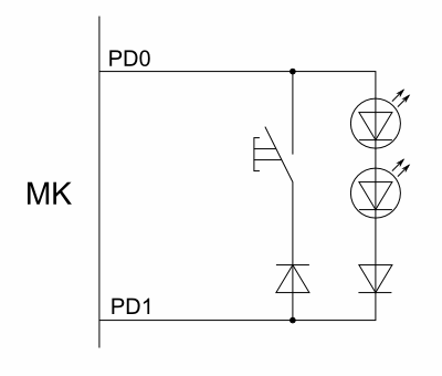
It works as follows: when you need to check the status of the button, feed the level “0” to PD0 and check PD1. When the button is pressed, “0” will appear there. To light the LED, we apply to PD0 "1", and to PD1 "0". Since the specificity of the game is to wait for someone to press a button, and only then light up its LED, it didn’t even take a dynamic display — first wait for pressing, then light the LED.
At the same time, there was an interesting point: everything worked fine in the debugger, and when testing on the layout at start-up, the pressed button was immediately detected. Having broken my head, I tried to add a delay between the initialization of the PD1 port to the input (with a pull-up resistor) and checking its state. It turned out that due to the capacity of long wires to the console (about 10 meters), the signal level did not immediately reach "1" due to the pull-up resistor. The delay was only a couple of microseconds, but the MC is fast and it turned out to be significant :)
UPD2: The firmware for the traffic light (source for ASM and compiled code) is here . Pay attention to lines 56-72, they contain the described logic of recognition of the type of reset.
Source: https://habr.com/ru/post/110894/
All Articles