Password generator that is always at hand
About how to invent good, resistant to the selection of passwords, written many articles, including on Habré. Today I want to tell about the device, which is also designed to solve this problem. It took me only a couple of days to develop it, and it can be made according to the finished documentation in a few hours. This device will look interesting on your desk, as well as serve as an original gift for a computer geek, a sysadmin or an information security specialist.
So, get acquainted: RANDOMOUSE is a random character generator built into a regular computer mouse.
')
To generate random numbers by an algorithmic method, we need a function that will produce the next value on each call. It is very desirable that these values “look” random (in the spread), and the repetition period of the sequence should be maximum (ideally 2 ^ N-1, where N is the bitness of the result).
The function of generating a pseudo-random number is a polynomial of the form

given by the coefficients gi = {0,1} (i = 0, ... k).
To calculate the value of a function, the Galois scheme can be used, as it is the simplest in an algorithmic implementation. The polynomial is given by its coefficients as a binary number, the value of the function f (x) is calculated by the algorithm.
1. If the least_bit (x) = 1, then
2. f (x) = (x / 2) xor Polynomial
3. otherwise
4. f (x) = x / 2
5. everything
In the next step, the calculated value is used as an argument of the function and everything is repeated. The least significant bit of the calculated value is used as the generator output.
There are polynomials, called primitive, that give a non-repeating sequence of values of a function of the maximum possible length. A deeper theory on this subject can be read, for example, here .
It is clear that any algorithm with the same input data gives the same result. Therefore, on the basis of purely algorithmic actions, it is possible to construct only a pseudo-random number generator — when the sequence of numbers at the output eventually repeats in the exact order. In this case, the sequence itself can be very long, but the main problem is that when the generator is initialized with the same input value, we always get the same sequence of numbers at the output.
To get a truly random sequence, in addition to the algorithmic generator, you need to use a physical one. The computer is constantly a lot of events that can be considered random with respect to the running program. This is the exchange of data with memory and drives, keyboard and mouse data entry, receiving packets from the network. In UNIX-like operating systems there is a built-in random number generator / dev / random, which outputs random data accumulated on the basis of such “physical noise”. This data can be used to generate the initial element of a sequence of random numbers or to constantly mix them into the result of the RNG's operation in order to obtain a truly random sequence.
In the considered password generator, both mechanisms of random number generation are used: algorithmic, based on a primitive polynomial, and physical. As a hardware random number sensor, one of the USB bus signal lines is used. During the data exchange between the mouse and the computer on this line, the signal is switched “randomly” between the values 0 and 1, which is used to add “physical noise” to the results of the algorithmic RNG.
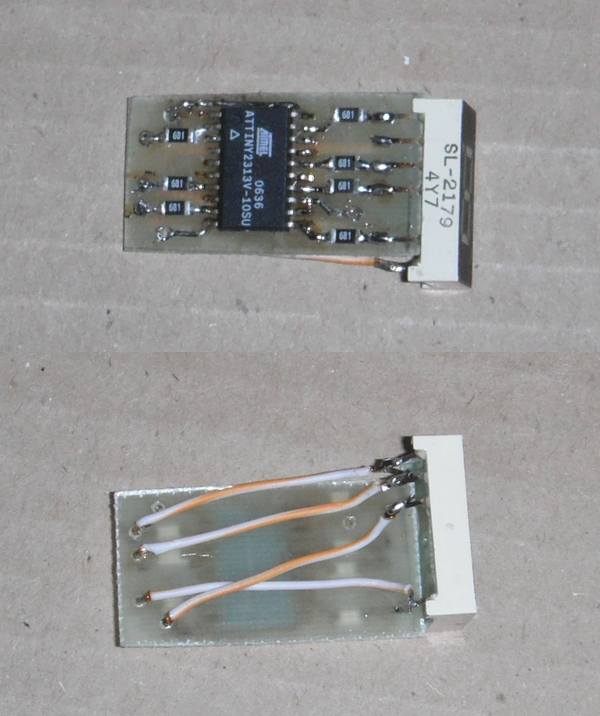
The generator is assembled on an Atmel 8-bit microcontroller from the AVR family. Thanks to the use of the microcontroller, the circuit turned out to be very simple; in addition to the MC, the indicator itself and several current-limiting resistors are also needed - one for each indicator discharge used.
I have developed two versions of the generator - for the usual 7-segment indicator and for the “advanced” 16-segment one. You could see the latter on modern household appliances that can communicate with the user in “human language”. This type of indicators allows you to display any of the letters of the Latin or Cyrillic alphabet. Unfortunately, I didn’t have a 16-segment indicator at hand, so “in the metal” I implemented only the 7-segment version, but I spread the schemes and firmware for both versions. In the case of a 7-segment indicator, the generator can display numbers and some letters.
Schematic diagram of both versions (click to enlarge)

Schemes, source code (in assembler) and compiled firmware for both versions can be downloaded as a zip-archive (44k) .
The values of the resistors are selected on the basis of the minimum current, which provides an acceptable luminosity of the indicator segments. You should not overload the USB port, although it can output a maximum of 500mA, it is usually programmed to 100mA, and to increase the limit, the connected device must indicate this in its descriptor.
The design of the device is mainly determined by the presence and shape of free space inside the mouse. Do not forget about the location of the indicator so that it can be seen. It is better that the indicator shines through the translucent wall of the case, then you will not have to cut a hole under it and the finished product will look better and more “branded”.

I placed the MK and resistors on a small fiberglass board made by a laser-iron method. The indicator is soldered for one row of legs, the board is connected to the legs of the second row by wires.
Inside the mouse, the indicator with the board was clamped between the two stiffening ribs of the sidewall of the case (the dimensions so well matched, even the glue was not needed).

Three wires (power, data and common) are soldered to the pins of the USB cable connector. The easiest way to determine the purpose of the wires with a tester, using the pinout USB-connector (see diagram).
To program the MK, thin conductors (from a twisted pair), to which the programmer was connected, were soldered directly to its conclusions. After checking the performance of the circuit, the conductors are unsoldered. I use USB USB programmer (http://www.fischl.de/usbasp/) and AVRDUDE (http://www.nongnu.org/avrdude/). For one-time programming (i.e., you only want to make this device, and not to do programming in the MK in the future) you can quickly assemble something from their circuits, for example, here (http://www.123avr.com/07). htm) or search for “AVR programmer” and read reviews about a specific circuit. The main thing is to make sure that the wires between the last active element of the programmer (buffer chip, PC chipset :), etc.) and MK are as short as possible.
If you want to upgrade your device, you will be interested to know how it works from the inside.
The USB interface uses 4 wires, denoted VCC (power, + 5V), Data- (D-), Data + (D +), GND (common). For data transfer, D + / D- lines are used, forming the so-called “differential pair”. According to the standard, when transmitting on one wire of a pair, the voltage should be not less than 2.7 Volt, and on the other not more than 0.3 Volt. When received, a logic zero level is considered to be a state in which the voltage on the D-line is not less than 0.2 Volt higher than the voltage on the D + line, and the level of the logical unit is vice versa. Due to the fact that these two wires are twisted into a twisted pair cable, this protocol provides high noise immunity during data transmission.
One of the wires of the pair is connected to the input of the analog comparator built into the MK. This device continuously compares the voltage at its two inputs and outputs a digital signal of 0 or 1, depending on which input voltage is higher. Theoretically, it would be possible to connect both wires of the pair to the comparator, but for the purpose of generating a random signal, one wire is sufficient. An internal voltage reference (approximately 1.1V) is connected to the second input.
The algorithm of the program is as follows:
1. When the power is turned on, the internal MK devices and I / O ports are initialized (lines 90-134). The port used for the comparator input should always be configured for input without connecting a pull-up resistor. Otherwise, the USB interface will not function. After initialization, the MC goes into sleep mode, so as not to waste energy.
2. The timer interrupt is called with a frequency equal to the number of possible values of a random number. Due to this, the frequency of changing values on the indicator remains equal to 1 second regardless of the number of values.
Immediately after the power is turned on, the device operates in demo mode, in turn displaying all possible values for 0.5 seconds each (lines 150-171).
Then there is a switch to the initial state of the RNG: the initial value of the algorithmic RNG from the physical sensor (lines 173-185).
After the initialization of the RNG, each subsequent operation of the timer results in the calculation of the next value of the RNG function and the addition of the low-order bit to the random value (lines 187-211). Every N cycles (where N is equal to the number of possible random values) the symbol corresponding to a random value is displayed (subroutine DISPLAY_SIGN in the included file depends on the number of segments), then the current random value is reset and the cycle starts over.
3. An analog comparator interrupt is called whenever its output value changes (from 0 to 1 or vice versa). To generate a physical random number, the current value of timer 0 is used, which continuously counts at the frequency of the MC (4 MHz). During the initialization of the RNG, the low-order bit of the timer 0 counter value is written to the low-order bit of the RNG variable, shifting the remaining bits to the high side (lines 234-244).
After 32 bits have been dialed, the device goes into operating mode. In it, the value of the lower 5 bits of timer counter 0 is added to a random value, after which a random value is taken modulo the number of possible values (lines 247-259).
For the convenience of switching between versions, all code, data and constants, depending on the digit capacity of the indicator, are moved to a separate file, which is included in the main code. You can create your own version based on the existing one.
Compliance with the outputs of the IC and the indicator segments are usually chosen based on the convenience of wiring conductors on the board. In case you change the connection scheme, you will also have to change the corresponding character generator table in the included file. If an indicator with a common anode (connected to + 5Volt) is used, then to ignite a segment at the output of the MK it should be 0, if with a common cathode (connected to a common wire), then 1.
Note that in the 16-bit version, 14 MC pins are actually used, the upper and lower pairs of segments are combined (but each is connected via its own resistor). This may impose restrictions on the display of characters. If you need to separate these segments, use the PA0, PA1 pins (they are not used in the internal generator mode) by changing the DISPLAY_SIGN subroutine.
Although new passwords do not have to be created too often, the described device may find other applications related to the generation of random numbers, for example, instead of a cube in board games. For convenience of work in various modes, you can select a mouse with additional buttons and connect one of them to the MC by updating the firmware so that when you press this button, tables of random characters are switched or the next random number is displayed.
Also, the proposed scheme with minimal changes can be used in other devices. The first thing that comes to mind on the New Year is to make a New Year's garland. To do this, instead of the indicator, LEDs are connected to the MK outputs (usually 5V voltage is enough for two LEDs connected in series, current limiting resistors can be not set if the current through the chain does not exceed 20mA), and ignition combinations of these LEDs are written in the character generator table. To connect chains of longer LEDs, you will need to increase the supply voltage (then the MK will need to be powered by a 5 Volt stabilizer) and use transistor switches or a specialized microchip buffer.
A separate question is what to do with the physical sensor (analog comparator input). It can be connected to a wire of sufficient length (30 centimeters should be enough), the resistance of the input MK is very high and the voltage at the input will change due to electromagnetic interference, creating the necessary random pulses. If the device is powered by USB (desktop souvenir "mini-herringbone"), the input can again be connected to any data line USB-bus.
So, get acquainted: RANDOMOUSE is a random character generator built into a regular computer mouse.
')
First a bit of theory
To generate random numbers by an algorithmic method, we need a function that will produce the next value on each call. It is very desirable that these values “look” random (in the spread), and the repetition period of the sequence should be maximum (ideally 2 ^ N-1, where N is the bitness of the result).
The function of generating a pseudo-random number is a polynomial of the form
given by the coefficients gi = {0,1} (i = 0, ... k).
To calculate the value of a function, the Galois scheme can be used, as it is the simplest in an algorithmic implementation. The polynomial is given by its coefficients as a binary number, the value of the function f (x) is calculated by the algorithm.
1. If the least_bit (x) = 1, then
2. f (x) = (x / 2) xor Polynomial
3. otherwise
4. f (x) = x / 2
5. everything
In the next step, the calculated value is used as an argument of the function and everything is repeated. The least significant bit of the calculated value is used as the generator output.
There are polynomials, called primitive, that give a non-repeating sequence of values of a function of the maximum possible length. A deeper theory on this subject can be read, for example, here .
It is clear that any algorithm with the same input data gives the same result. Therefore, on the basis of purely algorithmic actions, it is possible to construct only a pseudo-random number generator — when the sequence of numbers at the output eventually repeats in the exact order. In this case, the sequence itself can be very long, but the main problem is that when the generator is initialized with the same input value, we always get the same sequence of numbers at the output.
To get a truly random sequence, in addition to the algorithmic generator, you need to use a physical one. The computer is constantly a lot of events that can be considered random with respect to the running program. This is the exchange of data with memory and drives, keyboard and mouse data entry, receiving packets from the network. In UNIX-like operating systems there is a built-in random number generator / dev / random, which outputs random data accumulated on the basis of such “physical noise”. This data can be used to generate the initial element of a sequence of random numbers or to constantly mix them into the result of the RNG's operation in order to obtain a truly random sequence.
Generator device
In the considered password generator, both mechanisms of random number generation are used: algorithmic, based on a primitive polynomial, and physical. As a hardware random number sensor, one of the USB bus signal lines is used. During the data exchange between the mouse and the computer on this line, the signal is switched “randomly” between the values 0 and 1, which is used to add “physical noise” to the results of the algorithmic RNG.
The generator is assembled on an Atmel 8-bit microcontroller from the AVR family. Thanks to the use of the microcontroller, the circuit turned out to be very simple; in addition to the MC, the indicator itself and several current-limiting resistors are also needed - one for each indicator discharge used.
I have developed two versions of the generator - for the usual 7-segment indicator and for the “advanced” 16-segment one. You could see the latter on modern household appliances that can communicate with the user in “human language”. This type of indicators allows you to display any of the letters of the Latin or Cyrillic alphabet. Unfortunately, I didn’t have a 16-segment indicator at hand, so “in the metal” I implemented only the 7-segment version, but I spread the schemes and firmware for both versions. In the case of a 7-segment indicator, the generator can display numbers and some letters.
Schematic diagram of both versions (click to enlarge)
Schemes, source code (in assembler) and compiled firmware for both versions can be downloaded as a zip-archive (44k) .
The values of the resistors are selected on the basis of the minimum current, which provides an acceptable luminosity of the indicator segments. You should not overload the USB port, although it can output a maximum of 500mA, it is usually programmed to 100mA, and to increase the limit, the connected device must indicate this in its descriptor.
The design of the device is mainly determined by the presence and shape of free space inside the mouse. Do not forget about the location of the indicator so that it can be seen. It is better that the indicator shines through the translucent wall of the case, then you will not have to cut a hole under it and the finished product will look better and more “branded”.
I placed the MK and resistors on a small fiberglass board made by a laser-iron method. The indicator is soldered for one row of legs, the board is connected to the legs of the second row by wires.
Inside the mouse, the indicator with the board was clamped between the two stiffening ribs of the sidewall of the case (the dimensions so well matched, even the glue was not needed).
Three wires (power, data and common) are soldered to the pins of the USB cable connector. The easiest way to determine the purpose of the wires with a tester, using the pinout USB-connector (see diagram).
To program the MK, thin conductors (from a twisted pair), to which the programmer was connected, were soldered directly to its conclusions. After checking the performance of the circuit, the conductors are unsoldered. I use USB USB programmer (http://www.fischl.de/usbasp/) and AVRDUDE (http://www.nongnu.org/avrdude/). For one-time programming (i.e., you only want to make this device, and not to do programming in the MK in the future) you can quickly assemble something from their circuits, for example, here (http://www.123avr.com/07). htm) or search for “AVR programmer” and read reviews about a specific circuit. The main thing is to make sure that the wires between the last active element of the programmer (buffer chip, PC chipset :), etc.) and MK are as short as possible.
More about the scheme and firmware
If you want to upgrade your device, you will be interested to know how it works from the inside.
The USB interface uses 4 wires, denoted VCC (power, + 5V), Data- (D-), Data + (D +), GND (common). For data transfer, D + / D- lines are used, forming the so-called “differential pair”. According to the standard, when transmitting on one wire of a pair, the voltage should be not less than 2.7 Volt, and on the other not more than 0.3 Volt. When received, a logic zero level is considered to be a state in which the voltage on the D-line is not less than 0.2 Volt higher than the voltage on the D + line, and the level of the logical unit is vice versa. Due to the fact that these two wires are twisted into a twisted pair cable, this protocol provides high noise immunity during data transmission.
One of the wires of the pair is connected to the input of the analog comparator built into the MK. This device continuously compares the voltage at its two inputs and outputs a digital signal of 0 or 1, depending on which input voltage is higher. Theoretically, it would be possible to connect both wires of the pair to the comparator, but for the purpose of generating a random signal, one wire is sufficient. An internal voltage reference (approximately 1.1V) is connected to the second input.
The algorithm of the program is as follows:
1. When the power is turned on, the internal MK devices and I / O ports are initialized (lines 90-134). The port used for the comparator input should always be configured for input without connecting a pull-up resistor. Otherwise, the USB interface will not function. After initialization, the MC goes into sleep mode, so as not to waste energy.
2. The timer interrupt is called with a frequency equal to the number of possible values of a random number. Due to this, the frequency of changing values on the indicator remains equal to 1 second regardless of the number of values.
Immediately after the power is turned on, the device operates in demo mode, in turn displaying all possible values for 0.5 seconds each (lines 150-171).
Then there is a switch to the initial state of the RNG: the initial value of the algorithmic RNG from the physical sensor (lines 173-185).
After the initialization of the RNG, each subsequent operation of the timer results in the calculation of the next value of the RNG function and the addition of the low-order bit to the random value (lines 187-211). Every N cycles (where N is equal to the number of possible random values) the symbol corresponding to a random value is displayed (subroutine DISPLAY_SIGN in the included file depends on the number of segments), then the current random value is reset and the cycle starts over.
3. An analog comparator interrupt is called whenever its output value changes (from 0 to 1 or vice versa). To generate a physical random number, the current value of timer 0 is used, which continuously counts at the frequency of the MC (4 MHz). During the initialization of the RNG, the low-order bit of the timer 0 counter value is written to the low-order bit of the RNG variable, shifting the remaining bits to the high side (lines 234-244).
After 32 bits have been dialed, the device goes into operating mode. In it, the value of the lower 5 bits of timer counter 0 is added to a random value, after which a random value is taken modulo the number of possible values (lines 247-259).
For the convenience of switching between versions, all code, data and constants, depending on the digit capacity of the indicator, are moved to a separate file, which is included in the main code. You can create your own version based on the existing one.
Compliance with the outputs of the IC and the indicator segments are usually chosen based on the convenience of wiring conductors on the board. In case you change the connection scheme, you will also have to change the corresponding character generator table in the included file. If an indicator with a common anode (connected to + 5Volt) is used, then to ignite a segment at the output of the MK it should be 0, if with a common cathode (connected to a common wire), then 1.
Note that in the 16-bit version, 14 MC pins are actually used, the upper and lower pairs of segments are combined (but each is connected via its own resistor). This may impose restrictions on the display of characters. If you need to separate these segments, use the PA0, PA1 pins (they are not used in the internal generator mode) by changing the DISPLAY_SIGN subroutine.
Other uses
Although new passwords do not have to be created too often, the described device may find other applications related to the generation of random numbers, for example, instead of a cube in board games. For convenience of work in various modes, you can select a mouse with additional buttons and connect one of them to the MC by updating the firmware so that when you press this button, tables of random characters are switched or the next random number is displayed.
Also, the proposed scheme with minimal changes can be used in other devices. The first thing that comes to mind on the New Year is to make a New Year's garland. To do this, instead of the indicator, LEDs are connected to the MK outputs (usually 5V voltage is enough for two LEDs connected in series, current limiting resistors can be not set if the current through the chain does not exceed 20mA), and ignition combinations of these LEDs are written in the character generator table. To connect chains of longer LEDs, you will need to increase the supply voltage (then the MK will need to be powered by a 5 Volt stabilizer) and use transistor switches or a specialized microchip buffer.
A separate question is what to do with the physical sensor (analog comparator input). It can be connected to a wire of sufficient length (30 centimeters should be enough), the resistance of the input MK is very high and the voltage at the input will change due to electromagnetic interference, creating the necessary random pulses. If the device is powered by USB (desktop souvenir "mini-herringbone"), the input can again be connected to any data line USB-bus.
Source: https://habr.com/ru/post/110724/
All Articles