LED lamp with brightness control
Self-made LED lamp is equipped with a magnifying glass, and is designed for comfortable small-scale installation and disassembly with miniature radio parts - many hams know that it is difficult to see the marking on some SMD parts even under a magnifying glass. The presence of high-quality scattered backlighting significantly improves the marking reading, and simplifies the visual search for defects in electronic devices. Brief characteristics of the lamp:
- supply voltage of 12 volts DC, maximum power consumption of about 6..7 W, the number of LEDs - 20 pcs.
- built-in automatic calibration for power supply voltage.
- Smooth on and off the lamp.
- smooth brightness adjustment from zero to a pre-programmed limit - using the encoder knob. Power adjustment method - PWM (pulse width modulation).
- non-volatile memorization of all the parameters of the lamp and the last set brightness.
- built-in service menu available via USB connection. The menu allows you to adjust the operating parameters of the lamp and view its current state.
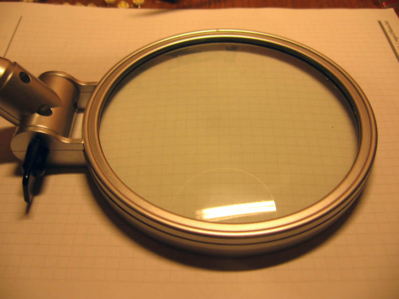
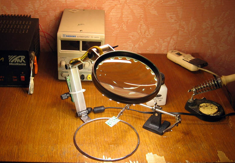
Magnifying lens on a tripod, which in the future will receive the backlight.

')
On the rim of the lens according to the plan should be installed LEDs.
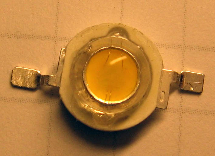
One-watt LEDs from the company ARL (Arlight), type OS-1W WarmWhite (75 Lm, 3000K, maximum allowable current 0.35 A), the color of the glow - white warm. At the maximum current, effective cooling of the LEDs is required so that they do not overheat above 85 degrees Celsius. For this, special radiators are usually used. However, I simplified my task - I installed the LEDs on a simple textolite ring, and limited the maximum current to 0.1 A, which automatically eliminated the cooling problem.

The appearance of a single LED. "Thick" output - the anode.
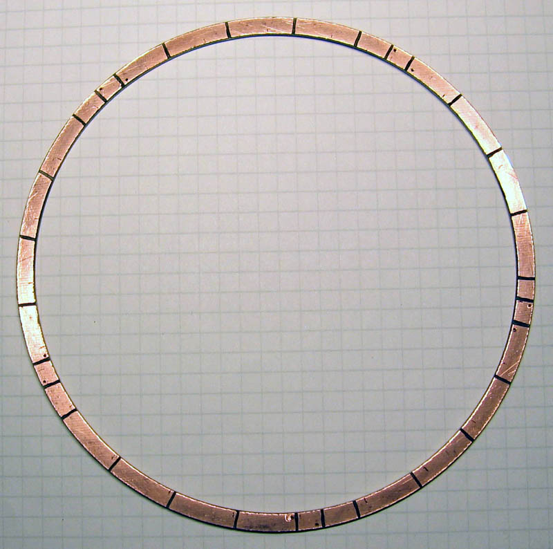
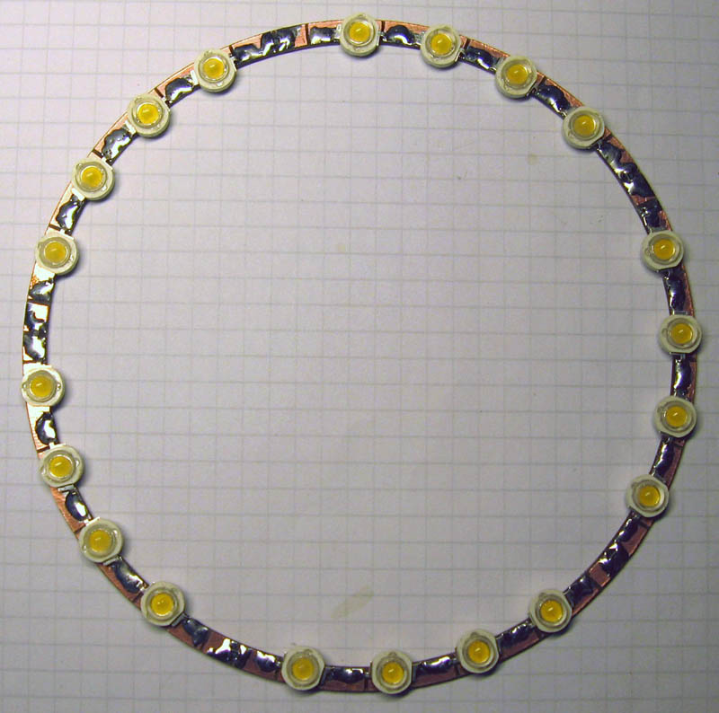
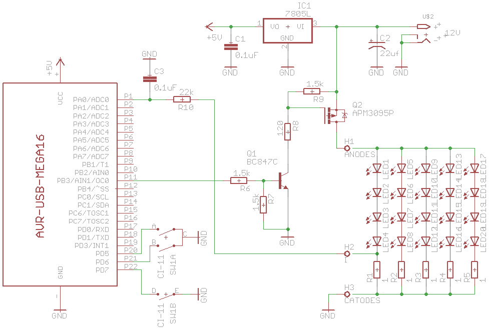
So, for fixing the LEDs from the double-sided foil textolite ring was cut. On the ring Dremel made wiring for 5 sections of LEDs, 4 LEDs and a resistor in each section. The resistor and the LEDs in each section are connected in series, and all sections are parallel to each other, due to which the array of LEDs turns out to be designed for 12 volts of supply voltage (see the circuit diagram below).

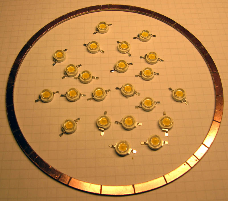
LEDs and SMD resistors were soldered to the ring. It turned out pretty nice.
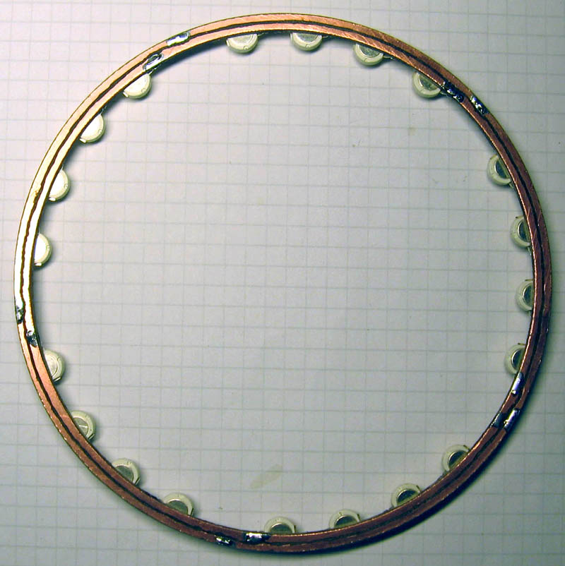
On the reverse side of the ring, a special groove was made by the Dremel, separating the copper ring along the length - we got two power buses that connect 5 sections of LEDs in parallel.

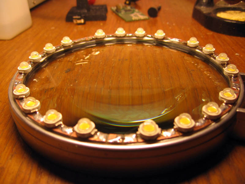
Thermally conductive glue "Radial" ring was glued to the rim of the lens. Although thermal conductivity did not help much here - the lens rim is still plastic.


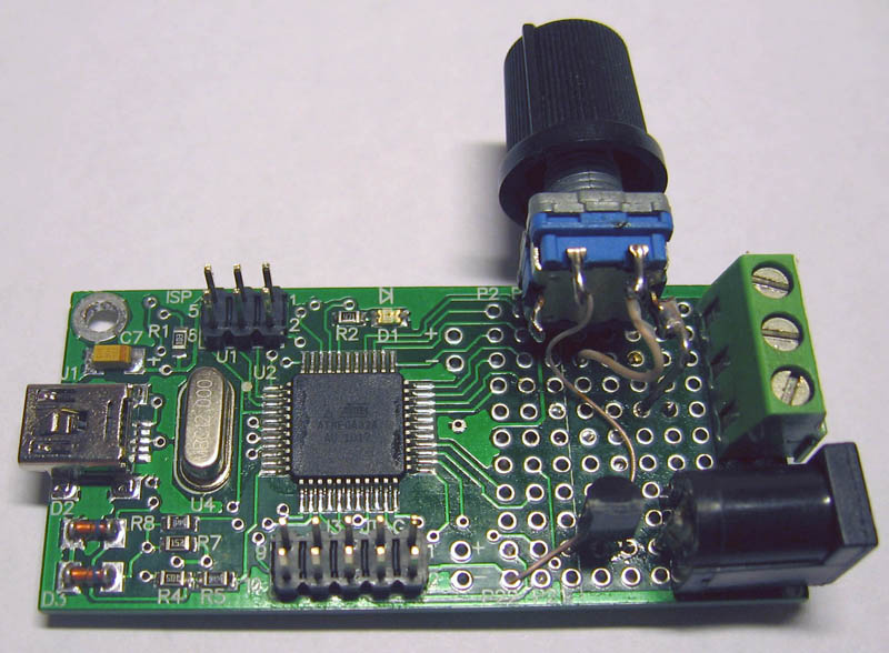
The AVR-USB-MEGA16 prototype board was used as a controller and driver for controlling the LEDs. It has a very convenient software update capability through a USB bootloader stitched into the board. On the prototyping field of the board a controller was doped. Due to the fact that everything was almost ready on the breadboard, the scheme was very simple. It was necessary to solder only the power part - the control of a key transistor, a voltage regulator of 5 volts and an RC-chain of the voltage filter from the current sensor output.
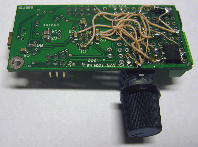
View of the finished mounted device from the reverse and upper side. The power transistor is used without a radiator, since small power is dissipated on it (it operates in key mode at a frequency of about 400 Hz).
Writing and debugging the program took a little time, because the algorithm of work is very simple, and ready-made pieces from other projects - ledlight, usb-console, encoder were used.

The lamp control console is made on the basis of the project “USB console for controlling amateur devices” (see references [2]). Edits were made minimal, and everything worked right away, debugging was not required.

A brief description of the algorithm - when the power is turned on, the settings from the EEPROM are read, and the lamp lights up with the brightness at which it was previously turned off. Rotating the encoder knob to the left gradually decreases the brightness, while rotating it to the right increases the brightness. The encoder also has a button which, when pressed, turns the lamp on and off. Turning on and off occurs with a smooth change in brightness - it looks pretty nice. If the encoder button was pressed when connecting external power, then all EEPROM settings are reset, and the program recalibrates the maximum limit of the regulation current - based on the resistance of the current sensor and the maximum permissible current.
The current through the LEDs is measured using the ADC built into the microcontroller (see references [3]). The PWM for power control is generated by the PWM node built into the microcontroller (see reference 4).
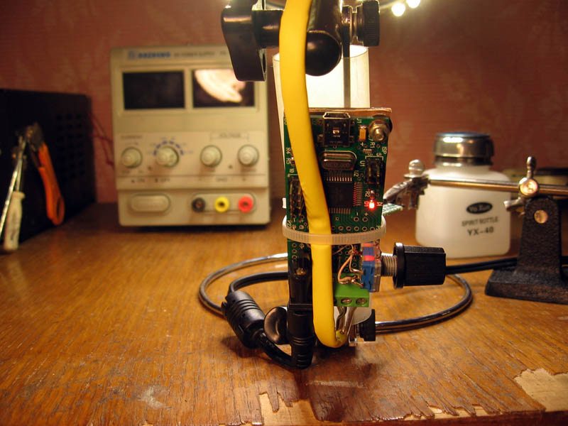
The wires from the lamp were collected in a cambric, and the controller was attached to the leg of the lens.

The result was a comfortable lamp that can be used for accurate radio installation.

Despite the fact that the maximum current through the LEDs was reduced three times (in order to protect against overheating), the lamp turned out very bright.
For boring technical details, see [1].
[ What can be improved in the design of the lamp ]
1 . For LEDs you can use a radiator. This will allow to reduce the number of used LEDs by 2..3 times with the same lamp brightness.
2 LEDs need some diffuser, because each LED individually glows very brightly, which is uncomfortable for the eye - even if you look at the LED from the side.
3 You can more accurately choose the resistance of the current sensor so that the voltage drop across it fits better to the reference voltage interval - this will improve the accuracy of current measurement. For low-resistance current sensors (1 ohm or less), the ADC can be switched to the differential input mode with a multiplication factor of X10.
4 To smooth the ripple current through the LEDs, increase the PWM frequency and put a choke in series with them (this is done in circuits with a hardware driver). This revision will increase the maximum allowable voltage of the circuit (it is now 12 volts). Another ADC channel can be used to measure the supply voltage of the LEDs - this will automatically stabilize the current through the LEDs when the supply voltage changes.
[ Links ]
1 . AVR-USB-MEGA16: LED controller / driver with brightness control. Sources, schematic diagram , documentation , photo .
2 USB console for controlling amateur radio devices .
3 ATmega16 (32): analog-to-digital converter (ADC) .
4 ATmega16 - PWM using T / C0, T / C1, T / C2 .
5 Features circuitry drivers superbright LEDs .
6 Drivers pumping white LEDs company National Semiconductor .
7 HV9910 - PWM driver for high-brightness LEDs (datashit in English) .
8 LT3474 / LT3474-1 - Step-Down 1A LED Driver (description in English) .
- supply voltage of 12 volts DC, maximum power consumption of about 6..7 W, the number of LEDs - 20 pcs.
- built-in automatic calibration for power supply voltage.
- Smooth on and off the lamp.
- smooth brightness adjustment from zero to a pre-programmed limit - using the encoder knob. Power adjustment method - PWM (pulse width modulation).
- non-volatile memorization of all the parameters of the lamp and the last set brightness.
- built-in service menu available via USB connection. The menu allows you to adjust the operating parameters of the lamp and view its current state.
Magnifying lens on a tripod, which in the future will receive the backlight.
')
On the rim of the lens according to the plan should be installed LEDs.
One-watt LEDs from the company ARL (Arlight), type OS-1W WarmWhite (75 Lm, 3000K, maximum allowable current 0.35 A), the color of the glow - white warm. At the maximum current, effective cooling of the LEDs is required so that they do not overheat above 85 degrees Celsius. For this, special radiators are usually used. However, I simplified my task - I installed the LEDs on a simple textolite ring, and limited the maximum current to 0.1 A, which automatically eliminated the cooling problem.
The appearance of a single LED. "Thick" output - the anode.
So, for fixing the LEDs from the double-sided foil textolite ring was cut. On the ring Dremel made wiring for 5 sections of LEDs, 4 LEDs and a resistor in each section. The resistor and the LEDs in each section are connected in series, and all sections are parallel to each other, due to which the array of LEDs turns out to be designed for 12 volts of supply voltage (see the circuit diagram below).
LEDs and SMD resistors were soldered to the ring. It turned out pretty nice.
On the reverse side of the ring, a special groove was made by the Dremel, separating the copper ring along the length - we got two power buses that connect 5 sections of LEDs in parallel.
Thermally conductive glue "Radial" ring was glued to the rim of the lens. Although thermal conductivity did not help much here - the lens rim is still plastic.
The AVR-USB-MEGA16 prototype board was used as a controller and driver for controlling the LEDs. It has a very convenient software update capability through a USB bootloader stitched into the board. On the prototyping field of the board a controller was doped. Due to the fact that everything was almost ready on the breadboard, the scheme was very simple. It was necessary to solder only the power part - the control of a key transistor, a voltage regulator of 5 volts and an RC-chain of the voltage filter from the current sensor output.
View of the finished mounted device from the reverse and upper side. The power transistor is used without a radiator, since small power is dissipated on it (it operates in key mode at a frequency of about 400 Hz).
Writing and debugging the program took a little time, because the algorithm of work is very simple, and ready-made pieces from other projects - ledlight, usb-console, encoder were used.
The lamp control console is made on the basis of the project “USB console for controlling amateur devices” (see references [2]). Edits were made minimal, and everything worked right away, debugging was not required.
A brief description of the algorithm - when the power is turned on, the settings from the EEPROM are read, and the lamp lights up with the brightness at which it was previously turned off. Rotating the encoder knob to the left gradually decreases the brightness, while rotating it to the right increases the brightness. The encoder also has a button which, when pressed, turns the lamp on and off. Turning on and off occurs with a smooth change in brightness - it looks pretty nice. If the encoder button was pressed when connecting external power, then all EEPROM settings are reset, and the program recalibrates the maximum limit of the regulation current - based on the resistance of the current sensor and the maximum permissible current.
The current through the LEDs is measured using the ADC built into the microcontroller (see references [3]). The PWM for power control is generated by the PWM node built into the microcontroller (see reference 4).
The wires from the lamp were collected in a cambric, and the controller was attached to the leg of the lens.
The result was a comfortable lamp that can be used for accurate radio installation.
Despite the fact that the maximum current through the LEDs was reduced three times (in order to protect against overheating), the lamp turned out very bright.
For boring technical details, see [1].
[ What can be improved in the design of the lamp ]
1 . For LEDs you can use a radiator. This will allow to reduce the number of used LEDs by 2..3 times with the same lamp brightness.
2 LEDs need some diffuser, because each LED individually glows very brightly, which is uncomfortable for the eye - even if you look at the LED from the side.
3 You can more accurately choose the resistance of the current sensor so that the voltage drop across it fits better to the reference voltage interval - this will improve the accuracy of current measurement. For low-resistance current sensors (1 ohm or less), the ADC can be switched to the differential input mode with a multiplication factor of X10.
4 To smooth the ripple current through the LEDs, increase the PWM frequency and put a choke in series with them (this is done in circuits with a hardware driver). This revision will increase the maximum allowable voltage of the circuit (it is now 12 volts). Another ADC channel can be used to measure the supply voltage of the LEDs - this will automatically stabilize the current through the LEDs when the supply voltage changes.
[ Links ]
1 . AVR-USB-MEGA16: LED controller / driver with brightness control. Sources, schematic diagram , documentation , photo .
2 USB console for controlling amateur radio devices .
3 ATmega16 (32): analog-to-digital converter (ADC) .
4 ATmega16 - PWM using T / C0, T / C1, T / C2 .
5 Features circuitry drivers superbright LEDs .
6 Drivers pumping white LEDs company National Semiconductor .
7 HV9910 - PWM driver for high-brightness LEDs (datashit in English) .
8 LT3474 / LT3474-1 - Step-Down 1A LED Driver (description in English) .
Source: https://habr.com/ru/post/110270/
All Articles