UART and what it eats
After Vogue hysteria, a lot of questions appeared on how to connect the board to the computer. And many people do not even understand what a UART is. And I decided to tell here what a powerful tool it is.
The router turns into a computer if you connect a keyboard and a display to it via UART
')
The UART protocol (Universal asynchronous receiver / transmitter) or, in Russian, UART (Universal Asynchronous Transceiver) is the oldest and most common physical data transfer protocol today. The most famous of the UART family is the RS-232 protocol (the people are the COM port, the one that is on your computer). This is probably the most ancient computer interface. He lived to the present day and did not lose its relevance.
It must be said that the UART interface originally appeared in the USA as a means for transmitting telegraph messages, and there were five working bits (as in Morse code). Mechanical devices were used for transmission. Then computers appeared, and ASCII codes, which required seven bits. In the early 60s, the well-known 8-bit ASCII table replaced everyone, and then the transmission format began to occupy a full-fledged byte, plus the control three bits.
In 1971, when the chip boom had already begun, Gordon Bell for Western Digital PDP computers made the UART WD1402A chip. At about the beginning of the 80s, the 8520 chip was created by National Semiconductor. In the 90s, a buffer was created for the interface, which allowed data to be transferred at higher speeds. This interface, having undergone almost no changes, has reached our days.
To understand what is related and distinguishes different UART-interfaces, let us examine the principle of operation of the most popular and beloved RS-232 protocol. I will not carefully describe all the details of his work. About a dozen megabytes of articles have been written about this, and if you know how to use Google, then without any problems you will find all the necessary information. But I will tell you the basics, the benefit with them is already cool to steer everything, and all kinds of chips are used very rarely.
Our main working lines are RXD and TXD, or simply RX and TX. The transmitting line is TXD (Transmitted Data) and the RXD port (Received Data) is the receiving one.
These lines of the COM port are involved in transmission without hardware flow control. With the hardware flow, additional interface lines (DTS, RTS, etc.) are also involved. The output of the transmitter TX is connected to the input of the receiver RX and vice versa. The electrical principle of RS-232 operation is different from the standard 5-volt TTL logic. In this protocol, logical zero is from +3 to +12 volts, and one is from -3 to -12, respectively. The interval from -3 to +3 volts is considered an area of uncertainty. Be aware that all voltages are relative to the computer case, or ground. Now, I think you understand why there are two voltages in a computer power supply at once: -12 and +12 volts. They were introduced specifically for the operation of the COM port.
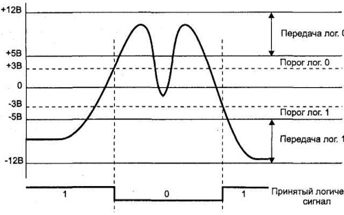
Signal reception via RS-232 (taken from M. Guk's book “PC Hardware Interfaces”)
Such a large amplitude of operating voltages, as much as 24 volts, is needed primarily for noise immunity of communication lines. According to the standard, the cable length over which we run data may be 15 m. Although in practice people managed to make it work even on 25 m. Electrical parameters of RS-232 are the main characteristic that distinguishes it from other UART family protocols.
The following characteristics - the sending format and data transfer rate - are fully applicable to all types of UART and ensure their compatibility through simple pairing schemes.
Standard parcel takes 10 bits. But this rule applies only to the standard settings of the COM port. In principle, it can be reconfigured so that it even understands the One-Wire interface. In idle mode, when nothing is transmitted through the line, it is in a state of logical one, or -12 volts. The start of the transfer is indicated by the transmission of the start bit, which is always zero. Then comes the transfer of eight bits of data. The parcel completes parity and stop bits. The parity bit checks the transmitted data. The start bit tells us that the data transfer is complete. It should be noted that the STOP bit can occupy 1, 1.5, and 2 bits. You should not think that these are fractional bits, this number speaks only about its duration. The stop bit, like the start bit, is zero.

UART signal on the oscilloscope screen. You can see the start bit, data and stop bit. Thanks DIHALT for the picture
Even if you have never had to work with a COM port before, at least in the modem you should know the nominal speeds: 9600, 28800, 33600, 56000, etc. How many bits per second escapes from our port? Look, let's say, the speed is 9600 bits per second. This means that the transmission of one bit will take 1/9600 seconds, and the transfer byte - 11/9600. And such a speed for a byte is true only if the stop bit will occupy one bit. In case it takes two stop bits, the transmission will be 12/9600. This is due to the fact that along with the data bits, special bits are also transmitted: start, stop and parity bits. The speed range of the COM port is standardized. As a rule, all devices operate at three standard speeds: 9600, 19200, 115200. But other options are possible, even the use of non-standard speeds or speeds that vary over time - I came across this when analyzing flights of the next device.
Types of UART there are a great many. I will not list their names, because if you speak English, you can google it yourself. But the most basic ones should be noted! Let me remind you that the main difference between the interfaces is in the environment and method of data transfer. Data can even be transmitted over fiber.
The second most common interface after RS-232 is RS-485. It is an industry standard, and the transmission in it is carried out over a twisted pair, which gives it a good noise immunity and increased transmission speed of up to 4 megabits per second. The length of the wire here can reach 1 km. As a rule, it is used in factories to control different machines.
I must say that IRDA, or infrared communication, which is built into most phones and PDAs, is also essentially a UART. Only data is transmitted not by wire, but with the help of infrared radiation.
In the SMART cards (SIM, satellite TV, bank cards) - the very devices that every self-respecting phreaker wants to buy - our favorite UART is also used. True, there is half-duplex data transfer, and the logic of work can be 1.8 / 3.3 and 5 volts. It looks like the RX is soldered with TX at one end and at the other - as a result, one transmits, the other at this moment is listening, and vice versa. This is governed by a standard smart card. So we know exactly how many bytes we will send, and how many cards will answer us. The topic is worth a separate article. In general, remember that UART is almost everywhere.
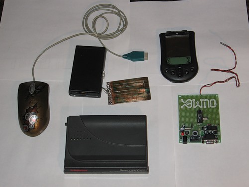
Devices that have UART on their boards are clockwise: mouse, SMART card reader emulator, Palm m105 PDA, debug board for ATtiny2313 (or AT89C2051) microcontroller, modem.
I already got sick of different interfaces, but how to work with them? Well, with the usual RS-232 is understandable, but, let's say, with a 5-volt yuart how to be? Everything is simple: there are various ready-to-chip converters. As a rule, in the marking they contain the numbers "232". I saw mikruhu in the scheme with these numbers - be sure: most likely, this is a converter. Through such chips with a small obvyazy and interfaced all interfaces UART. I will not talk about industrial interfaces, but I will say about those converters that interest us in the first place.
The most famous interface converter is a microcircuit developed by MAXIM, which received from it a part of its name (max232). Its operation requires four capacitors from 0.1 microfarad to 4 microfarads and power 5 volts. Surprisingly, this 5 volt chip generates a negative voltage to match a 5 volt UART with an RS-232.
There are USB interface chips with UART, for example, the chip ft232rl. Ubuntu already has drivers for this chip. For Windows, they will have to download from the official site. After installing the drivers, a virtual COM port will appear in the system, and with it you can already steer various devices. I advise you not to take these chips as the only possible ones. There will be a huge number of cheaper and more interesting analogues, therefore, press Google and you will understand that the world of UART is cool.
In general, chips are quite expensive and sometimes you can get by with more complex, but cheaper, circuits on a pair of transistors.
As you understand, the UART interface is present in many devices in which there is a processor or controller. I will even say more: if there is a controller there, then uart is stopudo (only it can not always be used). Typically, this interface is the adjustment and testing device. Often, the manufacturer is silent about the presence of this interface in the product, but it is easy to find it: you only need to download the manual to the processor and where you are located, you'll know. After you get physical access to the hardware through our interface, you can customize it to your liking or even make it work, because you need it, and not as planned by the manufacturer. In general, - to squeeze the maximum opportunities from a modest device. The knowledge of this protocol also gives the opportunity to overhear what is happening in the exchange lines between different processors, since manufacturers often organize entire user networks in their device. In general, there are many applications, the main thing is to intuitively understand how to do this.
The other day, I wowed my WL-520GU WiFi router and, after reading Step’s “Level-up for Access Point” article (] [# 106), I successfully installed Linux there. But I'm having problems mounting the swap partition of the hard disk. So there was a need to look at the boot log of the access point - whether the partition was mounted or not - and, as they say, on the fly, to immediately make the necessary changes. Sixth sense, I suspected that my router simply had to be a UART. I picked up the Phillips screwdriver and began to disassemble it. The case is trivial, but with a snag - secret cogs are under the rubber feet (if you decide to repeat, remember that when you parse you lose the warranty). My gaze presented a rather boring board, where all the “chip-in-one”: one central processor, which includes everything, an external operative, a flash, a power converter and a row of connectors with buttons. But on the board there was an unsoldered contact pad, more precisely, the holes for the needles. There were four of them. Here he UART, it is obvious! On the board, even without a multimeter, it can be seen that the extreme needles are +3.3 volts and the second is the ground. Average contacts, respectively, RX and TX. Which one of them is easy to install using the scientific method (to burn the interface is very problematic).
Just want to note that the UART interface in each router looks different. In most cases, it is not soldered holes on the board. True, in one ASUS router I even met a fully signed connector.
To connect a router to a computer, you need to pair the RS-232 interfaces with the router UART. In principle, you can connect to USB using the above FT232RL chip, which I did when I first checked the router. But this microcircuit is in a package rather complicated for soldering, therefore we will talk about simpler solutions. Namely - the MAX232 chip. If you are going to eat from a router, then there is likely to be 3.3 volts, so it’s best to use MAX3232, which usually stands in the PDA (the wiring diagram is not hard to find on the internet). But in my router there was a power supply of +5 volts at the input, and I have a great many of these microcircuits, and I did not bother. For the assembly, we will need 0.1 μF capacitors (4 pieces) and the microcircuit itself. We sealed everything according to the traditional scheme, and we begin the experiments.
Sources to build
On the way out, I immediately hung up a 9-pin male connector, so that you can easily connect a null modem cable. If you remember, at the time of DOS, such cables made a grid of two computers and were cut in "Dyuknyuky." Wire for our purposes to collect easy. True, it will not be a complete null modem and you will not play much through it, but the most important thing will be to steer the access point! You will need two 9-pin female connectors, the housing to them and a wire, for example, from an old mouse or keyboard (the main thing is that it has three wires). First we connect the earths ¬- this is the fifth contact of the connectors; just take any wire and solder it to the 5th contact from both sides. But with the RX and TX have to go smarter. From one end of a wire we solder on the 3rd contact, and from another - on the 2nd. Similarly, with the third wire, only from one end we solder to the 2nd contact, from the other - to the 3rd. The bottom line is that TX should transmit to RX. Hide the sealed connectors in the case - and a null modem cable is ready!
Soldered needles on the board of the router.
For ease of installation, I soldered the male connector into the motherboard of the router, and into the installer with the MAX232 - the reverse connector and inserted the scarf, as in a slot. RX and TX routers are selected experimentally.
Assembly fee
Now it is necessary to power the converter chip. The common wire is already present right in the connector on the router's mother. But +5 volt is located right at the router power input, in the place where the adapter is connected. The point of location of 5 volts is determined by a voltmeter, measuring different nodes relative to the ground of the router.
Connect the power. We include and begin our malicious experiments.

Burn the hole for the output wires
Soldered COM port

Everyone is here. Please note that the red power cord goes to the router adapter connector. The knot inside is made in order to pull off the soldered wires.
We need to configure a terminal program. In Windows, everything is quite simple: we start Hyper Terminal, disable software and hardware data verification, set the speed to 115200 and one stop bit. But in Linuheh the situation is a little trickier. I have Ubuntu, and I will talk about it. First, figure out how COM port is called in your build. In my case, COM1 was ttyS0 (if you use the FT232 chip for example, it will be called ttyUSB0). To work with him, I used the minicom softphone.
Run it with the parameters: minicom -l -8 -c on -s. Next, select "Serial Port Settings":
Serial port / dev / ttyS0
* Speed / parity / bits 115200 8N1
* Hardware flow control - no
* Software flow control - no
Save the settings. Software will try to initialize the modem - do not pay attention. To bring up the menu, press <ctrl-a z>. There you can change the settings, for example: turn on / off the echo - E.
Customization
I do not recommend connecting the converter chip to the router in order to test its functionality. It is only allowed to take power from it. Testing is very simple - you need to bridge the RX with the TX. First, you bridging the 2nd and 3rd contact in the COM port - you check the settings for the terminal. You write something on the clave: if the characters are returned, then everything is OK. Also check the cable, the same contacts. Then you plug in the microcircuit, and you put a jumper on it at the output. I focus on this, because, for example, I had problems, and nothing worked until I checked everything and found an error.
After all the settings, you can safely cling to the router and look for the RX-TX on the router, periodically pulling power from it. If everything is done correctly, then when power is applied, you will see the router download log. Accept congratulations, now you have a full hardware root, as if you are sitting at the monitor with the router's keyboard.
Log download router in minicom
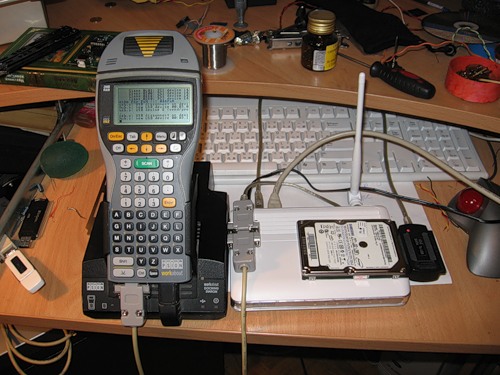
Agree to do the same through the terminal program, which is more convenient to do through SSH - not ice. I wanted to turn the router into a standalone Linux-based computer, with its cunning architecture. For this, it is necessary that the data from the keyboard be transmitted via the UART, and it is also displayed on the monitor. Soldering and developing the device was lazy. It was then that the idea came to open up for this purpose a dusty PDA. In fact, the handheld will play the role of a keyboard and display controller, and will also serve as a pairing interface.
At first I tried the most ancient Palm m100. But, apparently, he has a very small buffer memory, and from the amount of data that comes from the router, he felt bad. I took another - an industrial PDA, with a normal COM port and terminalka. I connected it, put it in the dock and, as a result, got a small Linux computer. In principle, instead of expensive industrial PDA, most handhelds operating under WinCE will work, the main thing is to find a suitable terminal software.
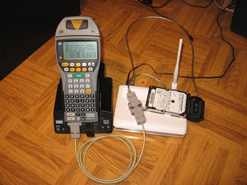
Linux computer :)
So, I showed a small example of using the UART. If you taste in this protocol, then believe me, you will become just the master of various glands. There is it almost everywhere, and through it you can match, it would seem, completely different things. For example, besides a router with small settings, a mobile phone is connected via Uarth, and it distributes the Internet from it. In general, a bunch of applications. Do not be afraid to experiment, self-educate and realize your ideas.
This post is the edited for habr version of my article in Hacker No. 05/09 "The main tool of the phreaker".
Literature:
1. Mikhail Guk "Hardware Interfaces PC" - just a student bible on personalke.
2. en.wikipedia.org/wiki/RS-232
3. easyelectronics.ru/tag/rs232
The router turns into a computer if you connect a keyboard and a display to it via UART
From telegraph to COM port
')
The UART protocol (Universal asynchronous receiver / transmitter) or, in Russian, UART (Universal Asynchronous Transceiver) is the oldest and most common physical data transfer protocol today. The most famous of the UART family is the RS-232 protocol (the people are the COM port, the one that is on your computer). This is probably the most ancient computer interface. He lived to the present day and did not lose its relevance.
It must be said that the UART interface originally appeared in the USA as a means for transmitting telegraph messages, and there were five working bits (as in Morse code). Mechanical devices were used for transmission. Then computers appeared, and ASCII codes, which required seven bits. In the early 60s, the well-known 8-bit ASCII table replaced everyone, and then the transmission format began to occupy a full-fledged byte, plus the control three bits.
In 1971, when the chip boom had already begun, Gordon Bell for Western Digital PDP computers made the UART WD1402A chip. At about the beginning of the 80s, the 8520 chip was created by National Semiconductor. In the 90s, a buffer was created for the interface, which allowed data to be transferred at higher speeds. This interface, having undergone almost no changes, has reached our days.
Interface physics
To understand what is related and distinguishes different UART-interfaces, let us examine the principle of operation of the most popular and beloved RS-232 protocol. I will not carefully describe all the details of his work. About a dozen megabytes of articles have been written about this, and if you know how to use Google, then without any problems you will find all the necessary information. But I will tell you the basics, the benefit with them is already cool to steer everything, and all kinds of chips are used very rarely.
Our main working lines are RXD and TXD, or simply RX and TX. The transmitting line is TXD (Transmitted Data) and the RXD port (Received Data) is the receiving one.
These lines of the COM port are involved in transmission without hardware flow control. With the hardware flow, additional interface lines (DTS, RTS, etc.) are also involved. The output of the transmitter TX is connected to the input of the receiver RX and vice versa. The electrical principle of RS-232 operation is different from the standard 5-volt TTL logic. In this protocol, logical zero is from +3 to +12 volts, and one is from -3 to -12, respectively. The interval from -3 to +3 volts is considered an area of uncertainty. Be aware that all voltages are relative to the computer case, or ground. Now, I think you understand why there are two voltages in a computer power supply at once: -12 and +12 volts. They were introduced specifically for the operation of the COM port.
Signal reception via RS-232 (taken from M. Guk's book “PC Hardware Interfaces”)
Such a large amplitude of operating voltages, as much as 24 volts, is needed primarily for noise immunity of communication lines. According to the standard, the cable length over which we run data may be 15 m. Although in practice people managed to make it work even on 25 m. Electrical parameters of RS-232 are the main characteristic that distinguishes it from other UART family protocols.
The following characteristics - the sending format and data transfer rate - are fully applicable to all types of UART and ensure their compatibility through simple pairing schemes.
Standard parcel takes 10 bits. But this rule applies only to the standard settings of the COM port. In principle, it can be reconfigured so that it even understands the One-Wire interface. In idle mode, when nothing is transmitted through the line, it is in a state of logical one, or -12 volts. The start of the transfer is indicated by the transmission of the start bit, which is always zero. Then comes the transfer of eight bits of data. The parcel completes parity and stop bits. The parity bit checks the transmitted data. The start bit tells us that the data transfer is complete. It should be noted that the STOP bit can occupy 1, 1.5, and 2 bits. You should not think that these are fractional bits, this number speaks only about its duration. The stop bit, like the start bit, is zero.
UART signal on the oscilloscope screen. You can see the start bit, data and stop bit. Thanks DIHALT for the picture
Work speed
Even if you have never had to work with a COM port before, at least in the modem you should know the nominal speeds: 9600, 28800, 33600, 56000, etc. How many bits per second escapes from our port? Look, let's say, the speed is 9600 bits per second. This means that the transmission of one bit will take 1/9600 seconds, and the transfer byte - 11/9600. And such a speed for a byte is true only if the stop bit will occupy one bit. In case it takes two stop bits, the transmission will be 12/9600. This is due to the fact that along with the data bits, special bits are also transmitted: start, stop and parity bits. The speed range of the COM port is standardized. As a rule, all devices operate at three standard speeds: 9600, 19200, 115200. But other options are possible, even the use of non-standard speeds or speeds that vary over time - I came across this when analyzing flights of the next device.
Such a different protocol
Types of UART there are a great many. I will not list their names, because if you speak English, you can google it yourself. But the most basic ones should be noted! Let me remind you that the main difference between the interfaces is in the environment and method of data transfer. Data can even be transmitted over fiber.
The second most common interface after RS-232 is RS-485. It is an industry standard, and the transmission in it is carried out over a twisted pair, which gives it a good noise immunity and increased transmission speed of up to 4 megabits per second. The length of the wire here can reach 1 km. As a rule, it is used in factories to control different machines.
I must say that IRDA, or infrared communication, which is built into most phones and PDAs, is also essentially a UART. Only data is transmitted not by wire, but with the help of infrared radiation.
In the SMART cards (SIM, satellite TV, bank cards) - the very devices that every self-respecting phreaker wants to buy - our favorite UART is also used. True, there is half-duplex data transfer, and the logic of work can be 1.8 / 3.3 and 5 volts. It looks like the RX is soldered with TX at one end and at the other - as a result, one transmits, the other at this moment is listening, and vice versa. This is governed by a standard smart card. So we know exactly how many bytes we will send, and how many cards will answer us. The topic is worth a separate article. In general, remember that UART is almost everywhere.
Devices that have UART on their boards are clockwise: mouse, SMART card reader emulator, Palm m105 PDA, debug board for ATtiny2313 (or AT89C2051) microcontroller, modem.
Interface pairing
I already got sick of different interfaces, but how to work with them? Well, with the usual RS-232 is understandable, but, let's say, with a 5-volt yuart how to be? Everything is simple: there are various ready-to-chip converters. As a rule, in the marking they contain the numbers "232". I saw mikruhu in the scheme with these numbers - be sure: most likely, this is a converter. Through such chips with a small obvyazy and interfaced all interfaces UART. I will not talk about industrial interfaces, but I will say about those converters that interest us in the first place.
The most famous interface converter is a microcircuit developed by MAXIM, which received from it a part of its name (max232). Its operation requires four capacitors from 0.1 microfarad to 4 microfarads and power 5 volts. Surprisingly, this 5 volt chip generates a negative voltage to match a 5 volt UART with an RS-232.
There are USB interface chips with UART, for example, the chip ft232rl. Ubuntu already has drivers for this chip. For Windows, they will have to download from the official site. After installing the drivers, a virtual COM port will appear in the system, and with it you can already steer various devices. I advise you not to take these chips as the only possible ones. There will be a huge number of cheaper and more interesting analogues, therefore, press Google and you will understand that the world of UART is cool.
In general, chips are quite expensive and sometimes you can get by with more complex, but cheaper, circuits on a pair of transistors.
What does this give us?
As you understand, the UART interface is present in many devices in which there is a processor or controller. I will even say more: if there is a controller there, then uart is stopudo (only it can not always be used). Typically, this interface is the adjustment and testing device. Often, the manufacturer is silent about the presence of this interface in the product, but it is easy to find it: you only need to download the manual to the processor and where you are located, you'll know. After you get physical access to the hardware through our interface, you can customize it to your liking or even make it work, because you need it, and not as planned by the manufacturer. In general, - to squeeze the maximum opportunities from a modest device. The knowledge of this protocol also gives the opportunity to overhear what is happening in the exchange lines between different processors, since manufacturers often organize entire user networks in their device. In general, there are many applications, the main thing is to intuitively understand how to do this.
Updateable router
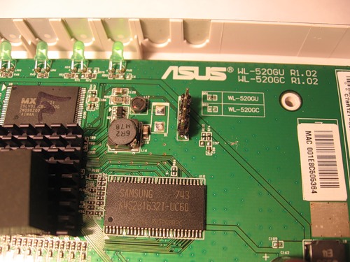
The other day, I wowed my WL-520GU WiFi router and, after reading Step’s “Level-up for Access Point” article (] [# 106), I successfully installed Linux there. But I'm having problems mounting the swap partition of the hard disk. So there was a need to look at the boot log of the access point - whether the partition was mounted or not - and, as they say, on the fly, to immediately make the necessary changes. Sixth sense, I suspected that my router simply had to be a UART. I picked up the Phillips screwdriver and began to disassemble it. The case is trivial, but with a snag - secret cogs are under the rubber feet (if you decide to repeat, remember that when you parse you lose the warranty). My gaze presented a rather boring board, where all the “chip-in-one”: one central processor, which includes everything, an external operative, a flash, a power converter and a row of connectors with buttons. But on the board there was an unsoldered contact pad, more precisely, the holes for the needles. There were four of them. Here he UART, it is obvious! On the board, even without a multimeter, it can be seen that the extreme needles are +3.3 volts and the second is the ground. Average contacts, respectively, RX and TX. Which one of them is easy to install using the scientific method (to burn the interface is very problematic).
Just want to note that the UART interface in each router looks different. In most cases, it is not soldered holes on the board. True, in one ASUS router I even met a fully signed connector.
We collect the converter
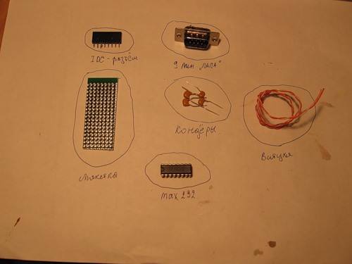
To connect a router to a computer, you need to pair the RS-232 interfaces with the router UART. In principle, you can connect to USB using the above FT232RL chip, which I did when I first checked the router. But this microcircuit is in a package rather complicated for soldering, therefore we will talk about simpler solutions. Namely - the MAX232 chip. If you are going to eat from a router, then there is likely to be 3.3 volts, so it’s best to use MAX3232, which usually stands in the PDA (the wiring diagram is not hard to find on the internet). But in my router there was a power supply of +5 volts at the input, and I have a great many of these microcircuits, and I did not bother. For the assembly, we will need 0.1 μF capacitors (4 pieces) and the microcircuit itself. We sealed everything according to the traditional scheme, and we begin the experiments.
Sources to build
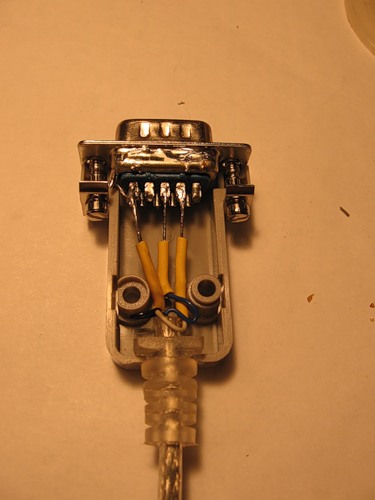
On the way out, I immediately hung up a 9-pin male connector, so that you can easily connect a null modem cable. If you remember, at the time of DOS, such cables made a grid of two computers and were cut in "Dyuknyuky." Wire for our purposes to collect easy. True, it will not be a complete null modem and you will not play much through it, but the most important thing will be to steer the access point! You will need two 9-pin female connectors, the housing to them and a wire, for example, from an old mouse or keyboard (the main thing is that it has three wires). First we connect the earths ¬- this is the fifth contact of the connectors; just take any wire and solder it to the 5th contact from both sides. But with the RX and TX have to go smarter. From one end of a wire we solder on the 3rd contact, and from another - on the 2nd. Similarly, with the third wire, only from one end we solder to the 2nd contact, from the other - to the 3rd. The bottom line is that TX should transmit to RX. Hide the sealed connectors in the case - and a null modem cable is ready!
Soldered needles on the board of the router.
For ease of installation, I soldered the male connector into the motherboard of the router, and into the installer with the MAX232 - the reverse connector and inserted the scarf, as in a slot. RX and TX routers are selected experimentally.
Assembly fee
Now it is necessary to power the converter chip. The common wire is already present right in the connector on the router's mother. But +5 volt is located right at the router power input, in the place where the adapter is connected. The point of location of 5 volts is determined by a voltmeter, measuring different nodes relative to the ground of the router.
Connect the power. We include and begin our malicious experiments.
Burn the hole for the output wires
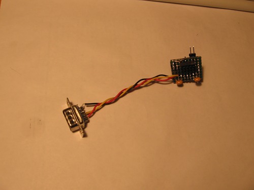
Soldered COM port
Everyone is here. Please note that the red power cord goes to the router adapter connector. The knot inside is made in order to pull off the soldered wires.
Terminal setup
We need to configure a terminal program. In Windows, everything is quite simple: we start Hyper Terminal, disable software and hardware data verification, set the speed to 115200 and one stop bit. But in Linuheh the situation is a little trickier. I have Ubuntu, and I will talk about it. First, figure out how COM port is called in your build. In my case, COM1 was ttyS0 (if you use the FT232 chip for example, it will be called ttyUSB0). To work with him, I used the minicom softphone.
Run it with the parameters: minicom -l -8 -c on -s. Next, select "Serial Port Settings":
Serial port / dev / ttyS0
* Speed / parity / bits 115200 8N1
* Hardware flow control - no
* Software flow control - no
Save the settings. Software will try to initialize the modem - do not pay attention. To bring up the menu, press <ctrl-a z>. There you can change the settings, for example: turn on / off the echo - E.
Customization
I do not recommend connecting the converter chip to the router in order to test its functionality. It is only allowed to take power from it. Testing is very simple - you need to bridge the RX with the TX. First, you bridging the 2nd and 3rd contact in the COM port - you check the settings for the terminal. You write something on the clave: if the characters are returned, then everything is OK. Also check the cable, the same contacts. Then you plug in the microcircuit, and you put a jumper on it at the output. I focus on this, because, for example, I had problems, and nothing worked until I checked everything and found an error.
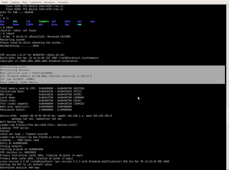
After all the settings, you can safely cling to the router and look for the RX-TX on the router, periodically pulling power from it. If everything is done correctly, then when power is applied, you will see the router download log. Accept congratulations, now you have a full hardware root, as if you are sitting at the monitor with the router's keyboard.
Log download router in minicom
Autonomous swimming
Agree to do the same through the terminal program, which is more convenient to do through SSH - not ice. I wanted to turn the router into a standalone Linux-based computer, with its cunning architecture. For this, it is necessary that the data from the keyboard be transmitted via the UART, and it is also displayed on the monitor. Soldering and developing the device was lazy. It was then that the idea came to open up for this purpose a dusty PDA. In fact, the handheld will play the role of a keyboard and display controller, and will also serve as a pairing interface.
At first I tried the most ancient Palm m100. But, apparently, he has a very small buffer memory, and from the amount of data that comes from the router, he felt bad. I took another - an industrial PDA, with a normal COM port and terminalka. I connected it, put it in the dock and, as a result, got a small Linux computer. In principle, instead of expensive industrial PDA, most handhelds operating under WinCE will work, the main thing is to find a suitable terminal software.
Linux computer :)
Results
So, I showed a small example of using the UART. If you taste in this protocol, then believe me, you will become just the master of various glands. There is it almost everywhere, and through it you can match, it would seem, completely different things. For example, besides a router with small settings, a mobile phone is connected via Uarth, and it distributes the Internet from it. In general, a bunch of applications. Do not be afraid to experiment, self-educate and realize your ideas.
This post is the edited for habr version of my article in Hacker No. 05/09 "The main tool of the phreaker".
Literature:
1. Mikhail Guk "Hardware Interfaces PC" - just a student bible on personalke.
2. en.wikipedia.org/wiki/RS-232
3. easyelectronics.ru/tag/rs232
Source: https://habr.com/ru/post/109395/
All Articles