Getting and outputting GPS coordinates on Arduino
Once I had an interest in GPS, and a little earlier - to the Arduino platform. Therefore, Sparkfun ordered a couple of days apart, Arduino Duemilanove, GPS Shield and GPS receiver EM-406A .
The order came and partially lay on the shelf, and recently got around to this set ...
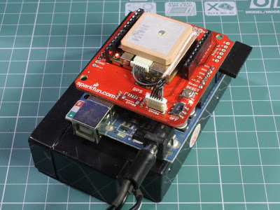
For greater mobility, the platform is powered by a separate battery and is connected to the computer only to fill in a new sketch.

')
In the presence of the shield pinout, by and large, is not so important - you just need to insert two connectors. If the shield is absent, then you need to connect the GND pins to GND, Rx - to digital pin 2, Tx - to digital pin 3, VCC - to POWER 5V. Attention, gray wire is not 1, but 6th!
The GPS module has a LED status indicator:
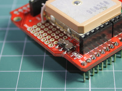
Using the switch, you can connect the Rx and Tx GPS module to the Tx and Rx Arduino feet (UART position) or to pin digital 2 and digital 3 (DLINE position, if you do not remove the jumpers from the solder). You need to make sure that the switch is in the “DLINE” position, otherwise there may be problems with filling the sketches in the Arduino.
I did not buy a separate shield under the screen and connected an already existing indicator - WH-0802A in 4-bit mode. In principle, any other symbolic indicator can be connected this way. To do this, find the pinout pinout in the datasheet and connect the RS, E, D4, D5, D6, D7 lines to any digital pins (except 0 ... 3) and remember to configure where these lines are connected in the code, Vss, R / W - to GND, Vdd - to 5V. Vo output (contrast setting) needs to be connected to a potentiometer connected between GND and 5V, but I just plugged in to GND - the resulting contrast suited me.
To work with GPS, you will need two libraries TinyGPS and NewSoftSerial . Libraries are unpacked into the libraries directory.
After turning on the GPS module and filling in the sketch, you need to wait at least 42 seconds (cold start time) in order for the module to determine its location and start issuing valid coordinates. When the module enters the operating mode, it will blink the LED. On my desktop, the module can not always find satellites - you have to transfer it to the window.

A power supply for the backlight is connected to the right of the display.
After determining the satellites, the coordinates appear on the display and are updated once a second.
As a result, the experience and the basis for the further development of GPS.
The order came and partially lay on the shelf, and recently got around to this set ...
Assembled GPS Shield connected to Arduino
Hardware
- Arduino Duemilanove
- GPS Shield
- GPS receiver EM-406A
- LCD WH-0802A
For greater mobility, the platform is powered by a separate battery and is connected to the computer only to fill in a new sketch.
Pinout GPS module EM-406A
')
In the presence of the shield pinout, by and large, is not so important - you just need to insert two connectors. If the shield is absent, then you need to connect the GND pins to GND, Rx - to digital pin 2, Tx - to digital pin 3, VCC - to POWER 5V. Attention, gray wire is not 1, but 6th!
The GPS module has a LED status indicator:
- the indicator is on constantly - satellites are being searched for and coordinates are being determined
- the indicator blinks - the coordinates are set, they are being transmitted
- the indicator is off, the power to the shield is on - poor contact in the connectors or the module has switched to the binary SiRF protocol
UART / DLINE switch
Using the switch, you can connect the Rx and Tx GPS module to the Tx and Rx Arduino feet (UART position) or to pin digital 2 and digital 3 (DLINE position, if you do not remove the jumpers from the solder). You need to make sure that the switch is in the “DLINE” position, otherwise there may be problems with filling the sketches in the Arduino.
Connecting Synthetic LCD Indicator
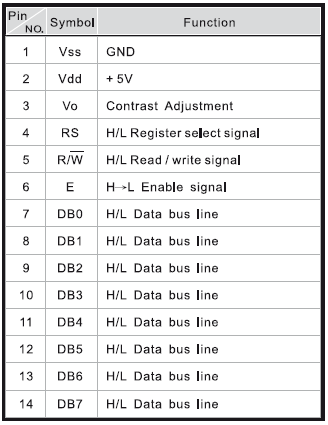
I did not buy a separate shield under the screen and connected an already existing indicator - WH-0802A in 4-bit mode. In principle, any other symbolic indicator can be connected this way. To do this, find the pinout pinout in the datasheet and connect the RS, E, D4, D5, D6, D7 lines to any digital pins (except 0 ... 3) and remember to configure where these lines are connected in the code, Vss, R / W - to GND, Vdd - to 5V. Vo output (contrast setting) needs to be connected to a potentiometer connected between GND and 5V, but I just plugged in to GND - the resulting contrast suited me.
WH-0802A indicator pin assignment
My version of connecting the indicator to the Arduino
- RS - pin 13
- E - pin 12
- D4 - pin 11
- D5 - pin 10
- D6 - pin 9
- D7 - pin 8
- Vss, R / W, Vo - GND
- Vdd - 5V
Software part
To work with GPS, you will need two libraries TinyGPS and NewSoftSerial . Libraries are unpacked into the libraries directory.
#include <NewSoftSerial.h>
#include <TinyGPS.h>
#include <LiquidCrystal.h>
TinyGPS gps;
//Tx, Rx
NewSoftSerial nss(2, 3);
// , lcd: RS, E, D4, D5, D6, D7
LiquidCrystal lcd(13, 12, 11, 10, 9, 8);
bool feedgps();
void setup() {
//4800 GPS
nss.begin(4800);
//8 , 2
lcd.begin(8, 2);
lcd.print( "waiting" );
}
void loop() {
bool newdata = false ;
unsigned long start = millis();
long lat, lon;
unsigned long age;
//
while (millis() - start < 1000) {
if (readgps())
newdata = true ;
}
if (newdata) {
gps.get_position(&lat, &lon, &age);
lcd.setCursor(0, 0);
lcd.print(lat);
lcd.setCursor(0, 1);
lcd.print(lon);
}
}
bool readgps() {
while (nss.available()) {
int b = nss.read();
// TinyGPS , \r \n
if ( '\r' != b) {
if (gps.encode(b))
return true ;
}
}
return false ;
}
After turning on the GPS module and filling in the sketch, you need to wait at least 42 seconds (cold start time) in order for the module to determine its location and start issuing valid coordinates. When the module enters the operating mode, it will blink the LED. On my desktop, the module can not always find satellites - you have to transfer it to the window.
A working module with a connected display and received coordinates
A power supply for the backlight is connected to the right of the display.
After determining the satellites, the coordinates appear on the display and are updated once a second.
As a result, the experience and the basis for the further development of GPS.
"Used Books"
Source: https://habr.com/ru/post/108797/
All Articles