Telephony on Cisco (Call Manager Express) - Part 2
The second part will discuss the use of E1 digital trunks that can be used to connect the router to the PBX
')
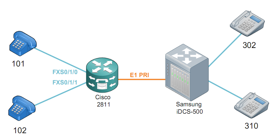
We have a Cisco2811 router with an NM-HDV2 module installed in the NM slot and a VWIC2-1MFT-T1 / E1 card; in the same module, an 8-channel PVDM is installed.
Also, the router has a VIC2-2FXS module for connecting analog phones.
As a PBX, a Samsung iDCS-500 digital PBX with a TEPRI board was used to connect via E1 and an 8-DLI board, to which 2 OfficeServ KPDP-14SED phones are connected.
To activate the module, we determine in which mode (E1 or T1) it will work.
You can do the following to check the health of the interface:
If you wish, you can create several serial subinterfaces with different bandwidths (depending on the number of timeslots)
after this operation, we have a new interface Serial1 / 0/0: 1
Next you need to make a hardware loopback, take the RJ-45 connector and 2 wiring from a twisted pair with a length of about 10 cm. Insert the first wire into pins 1 and 4, and the second into pins 2 and 5. Compress all this stuff and get a loopback plug.
We insert it into the E1 interface, the CD LED (Carrier detect) lights up green, the Serial1 / 0/0: 1 interface changes to the up state, the interface is working
The configuration of the analog ports was considered in the first part, I will not dwell in detail. For analog phones, add:
Putting the E1 controller in PRI mode:
The number of time slots depends on the available PVDM, in case of insufficient resources an error message will appear. The command entered above allows using the first 10 timeslots for a voice, i.e. in our trunk there can be no more than 10 simultaneous conversations. The 16th timeslot is used for signaling.
Configuring the signaling channel - this is the 15th subinterface of the Serial1 / 0/0 interface that appears after the controller configuration
Configure the dial plan for outgoing calls:
The configuration of the router on this can be considered complete, to connect to the PBX you need to use a cross-cable with two RJ45 and pinout
In addition, you need to make sure that the TEPRI board is properly configured, it must be set to Network mode (station part, by default, the board is in User mode for connecting to the higher-level PBX) and set the E1 operation mode.
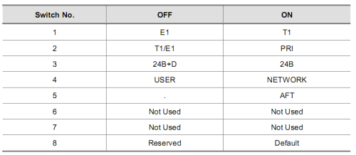
To do this, remove the case from the board and set the jumpers according to the table:
An internal numbering plan must also be configured on the PBX (in my case, 3xx)
If everything is configured correctly, then when dialing, the corresponding phone on the PBX should ring, the phone number should display the analog phone from which the call was made.
In an outgoing call, one of the sub-interfaces is raised:
After the call, you can check the status of the signaling channel with the show isdn status command:
We try 2 simultaneous calls:
Put the tube:
The list of active calls can be viewed with the show isdn active command.
You can also see the status of the PRI channel, for this we use the show isdn service command
It can be seen that with one active call, the 9th timeslot is in the Busy state (2)
Detailed call debugging can be done with the debug dial-peer and debug isdn q931 commands.
To check incoming calls, you can dial the number of the output to the corresponding channel on the PRI trunk on a digital phone, and then dial the number of one of the analog phones. When a call comes in, the sub interface corresponding to the selected channel on the PRI trunk should rise.
That's all, thank you for your attention.
To be continued…
ps found cool icons for the scheme under visio, you can download it here
')
1. Components of the circuit
We have a Cisco2811 router with an NM-HDV2 module installed in the NM slot and a VWIC2-1MFT-T1 / E1 card; in the same module, an 8-channel PVDM is installed.
Also, the router has a VIC2-2FXS module for connecting analog phones.
As a PBX, a Samsung iDCS-500 digital PBX with a TEPRI board was used to connect via E1 and an 8-DLI board, to which 2 OfficeServ KPDP-14SED phones are connected.
2. Basic router configuration
To activate the module, we determine in which mode (E1 or T1) it will work.
Router(config)#card type e1 1 0
#e1 - , 1 - NM-, 0 - wic-

#
Router#show controller e1
E1 1/0/0 is down.
Applique type is Channelized E1 - balanced
Transmitter is sending remote alarm.
Receiver has loss of signal.
alarm-trigger is not set
Version info Firmware: 20040802, FPGA: 13, spm_count = 0
Framing is CRC4, Line Code is HDB3, Clock Source is Line.
Current port master clock:local osc on this network module
Data in current interval (365 seconds elapsed):
0 Line Code Violations, 0 Path Code Violations
0 Slip Secs, 0 Fr Loss Secs, 0 Line Err Secs, 0 Degraded Mins
0 Errored Secs, 0 Bursty Err Secs, 0 Severely Err Secs, 365 Unavail Secs
You can do the following to check the health of the interface:
1 serial interface
Router(config)#controller E1 1/0/0
Router(config-controller)#channel-group 0 timeslots 1-31
0 - serial-c, 1-31 - ,
If you wish, you can create several serial subinterfaces with different bandwidths (depending on the number of timeslots)
after this operation, we have a new interface Serial1 / 0/0: 1
Next you need to make a hardware loopback, take the RJ-45 connector and 2 wiring from a twisted pair with a length of about 10 cm. Insert the first wire into pins 1 and 4, and the second into pins 2 and 5. Compress all this stuff and get a loopback plug.
We insert it into the E1 interface, the CD LED (Carrier detect) lights up green, the Serial1 / 0/0: 1 interface changes to the up state, the interface is working
The configuration of the analog ports was considered in the first part, I will not dwell in detail. For analog phones, add:
dial-peer voice 1 pots
destination-pattern 101
port 0/1/0
!
dial-peer voice 2 pots
destination-pattern 102
port 0/1/1
3. PRI trunk configuration
Putting the E1 controller in PRI mode:
controller E1 1/0/0
pri-group timeslots 1-10,16
The number of time slots depends on the available PVDM, in case of insufficient resources an error message will appear. The command entered above allows using the first 10 timeslots for a voice, i.e. in our trunk there can be no more than 10 simultaneous conversations. The 16th timeslot is used for signaling.
Configuring the signaling channel - this is the 15th subinterface of the Serial1 / 0/0 interface that appears after the controller configuration
interface Serial1/0/0:15

# PRI
isdn switch-type primary-net5
#
isdn incoming-voice voice
Configure the dial plan for outgoing calls:
dial-peer voice 3 pots
#dial-peer , "3"
destination-pattern 3..
# PRI,
port 1/0/0:15
forward-digits all
# direct-inward-dial
direct-inward-dial
The configuration of the router on this can be considered complete, to connect to the PBX you need to use a cross-cable with two RJ45 and pinout
1-4
2-5
4-1
5-2
In addition, you need to make sure that the TEPRI board is properly configured, it must be set to Network mode (station part, by default, the board is in User mode for connecting to the higher-level PBX) and set the E1 operation mode.
To do this, remove the case from the board and set the jumpers according to the table:
An internal numbering plan must also be configured on the PBX (in my case, 3xx)
If everything is configured correctly, then when dialing, the corresponding phone on the PBX should ring, the phone number should display the analog phone from which the call was made.
In an outgoing call, one of the sub-interfaces is raised:
Nov 16 16:21:58.799: %ISDN-6-CONNECT: Interface Serial1/0/0:9 is now connected to 302 N/A
4. Check and debug
After the call, you can check the status of the signaling channel with the show isdn status command:
Router#show isdn status
Global ISDN Switchtype = primary-net5
ISDN Serial1/0/0:15 interface
dsl 0, interface ISDN Switchtype = primary-net5
Layer 1 Status:
ACTIVE
Layer 2 Status:
TEI = 0, Ces = 1, SAPI = 0, State = MULTIPLE_FRAME_ESTABLISHED
Layer 3 Status:
1 Active Layer 3 Call(s)
#
CCB:callid=8004, sapi=0, ces=0, B-chan=10, calltype=VOICE
Active dsl 0 CCBs = 1
The Free Channel Mask: 0x800001FF
Number of L2 Discards = 0, L2 Session ID = 1
Total Allocated ISDN CCBs = 1
We try 2 simultaneous calls:
Nov 17 15:41:43.447: %ISDN-6-CONNECT: Interface Serial1/0/0:9 is now connected to 302 N/A
Nov 17 15:42:03.675: %ISDN-6-CONNECT: Interface Serial1/0/0:8 is now connected to 310 N/A
Put the tube:
Nov 17 15:42:51.979: %ISDN-6-DISCONNECT: Interface Serial1/0/0:9 disconnected from 310 , call lasted 68 seconds
Nov 17 15:42:59.467: %ISDN-6-DISCONNECT: Interface Serial1/0/0:8 disconnected from 302 , call lasted 55 seconds
The list of active calls can be viewed with the show isdn active command.
Router#sh isdn active
--------------------------------------------------------------------------------
ISDN ACTIVE CALLS
--------------------------------------------------------------------------------
Call Calling Called Remote Seconds Seconds Seconds Charges
Type Number Number Name Used Left Idle Units/Currency
--------------------------------------------------------------------------------
Out 101 302 104 Unavail - 0
--------------------------------------------------------------------------------
You can also see the status of the PRI channel, for this we use the show isdn service command
Router#sh isdn service
PRI Channel Statistics:
ISDN Se1/0/0:15, Channel [1-31]
Configured Isdn Interface (dsl) 0
Channel State (0=Idle 1=Proposed 2=Busy 3=Reserved 4=Restart 5=Maint_Pend)
Channel : 1 2 3 4 5 6 7 8 9 0 1 2 3 4 5 6 7 8 9 0 1 2 3 4 5 6 7 8 9 0 1
State : 0 0 0 0 0 0 0 0 0 2 3 3 3 3 3 3 3 3 3 3 3 3 3 3 3 3 3 3 3 3 3
Service State (0=Inservice 1=Maint 2=Outofservice 8=MaintPend 9=OOSPend)
Channel : 1 2 3 4 5 6 7 8 9 0 1 2 3 4 5 6 7 8 9 0 1 2 3 4 5 6 7 8 9 0 1
State : 0 0 0 0 0 0 0 0 0 0 2 2 2 2 2 2 2 2 2 2 2 2 2 2 2 2 2 2 2 2 2
It can be seen that with one active call, the 9th timeslot is in the Busy state (2)
Detailed call debugging can be done with the debug dial-peer and debug isdn q931 commands.
To check incoming calls, you can dial the number of the output to the corresponding channel on the PRI trunk on a digital phone, and then dial the number of one of the analog phones. When a call comes in, the sub interface corresponding to the selected channel on the PRI trunk should rise.
That's all, thank you for your attention.
To be continued…
ps found cool icons for the scheme under visio, you can download it here
Source: https://habr.com/ru/post/107903/
All Articles