3D Console Renderer
Have nothing to do? then maybe just write 3D Console Software Rendering?
Welcome under the cut!

Today I will tell you how to write the simplest software 3D renderer.
Without any optimizations (which is typical for programs of this kind), because My main goal is to tell how 3D rendering happens, and not to speed up its work.
The format of the article does not allow describing the essence of the algorithms used and explaining why, for example, transformation matrices look like this and not otherwise. In such cases, I will simply give a search keyword or link and write what it should do. Please treat with understanding :)
So, let's begin:
')
In our case, the simplest 3D renderer will include:
I will describe in general terms the algorithm for rendering one triangle (thus, it will be repeated for each triangle displayed on the screen).
ColorBuffer and ZBuffer in our case are just 2 80x25 arrays (this is for example, of course, it all depends on the size of the console). The first will store the console characters and, if you want, their color. The second is the depth values for each pixel. It can be float or double - any data type that is a floating point number. I implemented this in the form of a template class, where the template parameter is a data type stored in an array.
The rasterization algorithm is needed to build a pixel triangle from the specified three points on the screen with their x, y, z coordinates; In order to understand and realize this, I recommend reading ru.wikipedia.org/wiki/Algorithm_Bresenham to rasterize the line and then use it to rasterize the triangle: compgraphics.info/2D/triangle_rasterization.php
There are different algorithms for this purpose, use any that you like. The main thing is to implement the functionality of generating all points of the triangle / line by the specified screen coordinates (i.e., for example, it will be in the range of 0..79, 0..24).
Or you can take one that is implemented in me - there is a triangle rasterization function, which uses the raster line's line function, which calls the point rasterization function, which performs z-test and displays the point on the screen. (needle in egg, duck egg, etc.)
I don’t pay attention to the speed of work, because it is easier to follow the logic of work. In itself, of course, something can be optimized.
So, let us have a point with x, y, z coordinates set in three-dimensional space;
I will tell you how to perform the correct Model-View-Projection transformations to create a three-dimensional effect. As I said, we first make a four-dimensional vector (x, y, z, 1)
The very first to perform a Model transform. In essence, this is simply a transfer / rotation / compression / tension or another coordinate system transformation. It is necessary in order to easily move an object over time - for example, our object rotates a few degrees around the X axis every 10 ms. Accordingly, the coordinates of the model are stored as is, and we simply change the matrix defining this rotation.
I will give an example of the simplest three-dimensional transformation matrices - transfer, rotation, compression.
Accordingly, for more complex transformations, take their composition. I represent the vector as a column vector and multiply it by the matrix on the right. Accordingly, if you need to do the opposite - transpose the matrix and multiply in a different order. Note that the order of multiplication of the matrices themselves is important - if you want to rotate an object and then make a transfer, then multiply the transfer matrix by a turn and then by the coordinates of the radius vector of the point. The resulting vector will be the radius vector of the transformed point.
Matrix examples:
Rotation around other axes is done in the same way: just substitute the appropriate rotation matrix into the upper left 3x3 submatrix
Rotation around an arbitrary axis: in OpenGL, there is a function that can feed the rotation angle and axis direction (any), and it will generate a rotation matrix and multiply by it.
The function simply computes the rotation matrix, so I will not describe it here. You can write it yourself, google (called glRotate) or take it from my source (I already google it for you :)
Next, the conversion is performed View. Probably the easiest way to explain this through the concept of "camera". If you have played three-dimensional games, then you probably imagine that this is the point from which you are looking at the game world and the orientation of the camera in the space of this world. For this you need to perform the transformations inverse of the above. For example, if you need to look at the world from a point (1,2,3), then you need to make a transfer (-1, -2, -3). This is logical - imagine that the object of the 3D world has coordinates (a, b, c). Then its model matrix will be the corresponding one — the transfer a, b, c. If at the same time the camera looks at the world from the same point, then the view matrix will look like: transfer -a, -b, -c and as a result, when multiplying View * Model * (x, y, z, 1), we will get the original coordinates object - so the camera is in the same place as the object.
There still must be turns to set the orientation of the camera. In order not to complicate life to anyone, I can only say - google the function gluLookAt (this article is so big, I think you should not post the source here) or take my source - there is this function too. It generates the View matrix for the given coordinates of the camera position, gaze direction and vector up (without this vector, the camera orientation is obviously ambiguous).
What is the result of the matrix? Imagine that you have some initial coordinate system and you make a move / turn and get another coordinate system. This transformation is defined by some matrix. If the beginning of the new coordinate system coincides with the position of the camera, the 'z' axis is directed in the direction of gaze, and the 'y' is up, then the View transformation matrix is the inverse of this transformation . Of course, no one is looking for the inverse matrix — just inverse conversions are done immediately to get the ViewMatrix.
And finally, Projection. The projection matrix performs the transformation of coordinates from the pyramid of visibility (Frustum) into a single cube (with perspective), after which the point is already easy to display.
Frustum is the part of the world that is projected on the screen. It is a truncated pyramid with two triangles at the base.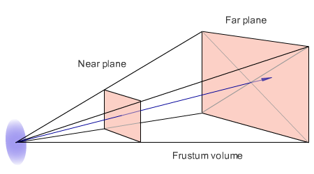
I also will not delve into the explanations about the device of the projection matrix, it is clear that it depends on the parameters znear, zfar (front and rear clipping planes), fovy (vertical viewing angle) and aspectratio (the ratio of the width of the colorbuffer to the height - in order the square looked like a square on a rectangular screen, not a rectangle). Google function gluPerspective or take from my source code.
In the end, our transformation looks like this: Projection * View * Model * (x, y, z, 1). At the final radius of the vector, divide the first 3 coordinates by the 4th and get a point ready for rendering and z-test.
It remains to translate everything in screen coordinates. Since we have matrix transformations that translate the coordinates of points into a cube [-1,1], and the coordinates of console points are 0..79 and 0..24, with simple operations you need to set the correct coordinates: (x + 1.0) * 0.5 * 80 and ( y + 1.0) * 0.5 * 25.
Now you need to run z-test. If the resulting value of z is greater than that which is already there, then the pixel should not be displayed on the screen. Otherwise, you need to write in the Color Buffer the color value of the pixel and in the z-buffer its z-coordinate.
Everything! You can download the demo and see!
The archive source and executable files for linux and windows
The article describes the simplest method of software rendering. Of course, in real-world projects, numerous optimizations are used, and the rendering process is much more complicated and with greater capabilities.
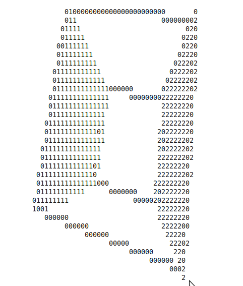
Finally, another screenshot from the ubuntu console:
Welcome under the cut!
Today I will tell you how to write the simplest software 3D renderer.
Without any optimizations (which is typical for programs of this kind), because My main goal is to tell how 3D rendering happens, and not to speed up its work.
The format of the article does not allow describing the essence of the algorithms used and explaining why, for example, transformation matrices look like this and not otherwise. In such cases, I will simply give a search keyword or link and write what it should do. Please treat with understanding :)
So, let's begin:
')
Introduction
In our case, the simplest 3D renderer will include:
- Color Buffer is just an array whose dimensions are equal to the size of the “screen”, and each cell stores the color of a “pixel” (in our case, the screen is a console with dimensions of, for example, 80x25, and a pixel is a symbol of the console — its “color” is Essence the character code and its color in the console)
- Depth Buffer is an array whose dimensions are the same as for Color Buffer-a, but it stores in itself the values of the “depth” of a given point. After all, since we are projecting three-dimensional space onto the screen, each point has a certain value of z coordinate along the axis perpendicular to the screen. We will need this so that in case of overlapping of some “pixels” by others, the pixel that is closer along the z-coordinate is displayed on the screen (z-test, more details - below)
- Rasterizer - in fact, it is an algorithm that generates all points forming a triangle of three given points (given the three points in the screen coordinates) and generates screen points lying on the line defined by their ends. This is due to the fact that we will use polygonal rendering, i.e. 3D-objects displayed on the screen are given by sets of triangles in three-dimensional space.
- Matrix transformations are actually transformations of triangles coordinates from source to screen (i.e., each point with x, y, z coordinates in three-dimensional space will be transformed into a point with x, y coordinates — points on the "screen" and z - depth value for z-buffer)).
I will describe in general terms the algorithm for rendering one triangle (thus, it will be repeated for each triangle displayed on the screen).
- The transformation of the coordinates of each vertex from the original coordinates to screen. For this purpose, so-called. “Homogeneous coordinates”. It is not necessary to know what it is, it is enough to understand how to use it. The bottom line is this: we assign the fourth coordinate w = 1 to each vertex. Then we multiply by 3 matrices - World, View, Projection, then we take the vertex with coordinates x / w, y / w, z / w and linearly convert the coordinates x and y to the coordinates of a point on the screen (specific description - below)
- Next, using the rasterizer of three points on the screen, we obtain the screen coordinates of all points of the triangle and perform a z-test for each point. Z-test is a comparison of the depth of a point on the screen with the depth of the point that we want to display. If the output point lies "further" than the one that already exists, then nothing needs to be output. Thus, we can draw 3D objects in any order, without worrying about which ones are closer and which ones are next. If we have a z-test, then everything will turn out automatically - nearby objects will close distant ones.
- After that you just need to display a point on the screen. For this, the “color of the point” is recorded in the Color Buffer, and its depth in the z-buffer.
Step 1. Color buffer and z-buffer
ColorBuffer and ZBuffer in our case are just 2 80x25 arrays (this is for example, of course, it all depends on the size of the console). The first will store the console characters and, if you want, their color. The second is the depth values for each pixel. It can be float or double - any data type that is a floating point number. I implemented this in the form of a template class, where the template parameter is a data type stored in an array.
Step 2. Rasterizer
The rasterization algorithm is needed to build a pixel triangle from the specified three points on the screen with their x, y, z coordinates; In order to understand and realize this, I recommend reading ru.wikipedia.org/wiki/Algorithm_Bresenham to rasterize the line and then use it to rasterize the triangle: compgraphics.info/2D/triangle_rasterization.php
There are different algorithms for this purpose, use any that you like. The main thing is to implement the functionality of generating all points of the triangle / line by the specified screen coordinates (i.e., for example, it will be in the range of 0..79, 0..24).
Or you can take one that is implemented in me - there is a triangle rasterization function, which uses the raster line's line function, which calls the point rasterization function, which performs z-test and displays the point on the screen. (needle in egg, duck egg, etc.)
I don’t pay attention to the speed of work, because it is easier to follow the logic of work. In itself, of course, something can be optimized.
Step 3. Coordinate Transformation
So, let us have a point with x, y, z coordinates set in three-dimensional space;
I will tell you how to perform the correct Model-View-Projection transformations to create a three-dimensional effect. As I said, we first make a four-dimensional vector (x, y, z, 1)
The very first to perform a Model transform. In essence, this is simply a transfer / rotation / compression / tension or another coordinate system transformation. It is necessary in order to easily move an object over time - for example, our object rotates a few degrees around the X axis every 10 ms. Accordingly, the coordinates of the model are stored as is, and we simply change the matrix defining this rotation.
I will give an example of the simplest three-dimensional transformation matrices - transfer, rotation, compression.
Accordingly, for more complex transformations, take their composition. I represent the vector as a column vector and multiply it by the matrix on the right. Accordingly, if you need to do the opposite - transpose the matrix and multiply in a different order. Note that the order of multiplication of the matrices themselves is important - if you want to rotate an object and then make a transfer, then multiply the transfer matrix by a turn and then by the coordinates of the radius vector of the point. The resulting vector will be the radius vector of the transformed point.
Matrix examples:
(Translation)
(x,y,z) -

1 0 0 x
0 1 0 y
0 0 1 z
0 0 0 1

/ (Scale)
(x,y,z) -
x 0 0 0
0 y 0 0
0 0 z 0
0 0 0 1
α (Rotate)
1 0 0 0
0 cos α -sin α 0
0 sin α cos α 0
0 0 0 1
Rotation around other axes is done in the same way: just substitute the appropriate rotation matrix into the upper left 3x3 submatrix
Rotation around an arbitrary axis: in OpenGL, there is a function that can feed the rotation angle and axis direction (any), and it will generate a rotation matrix and multiply by it.
The function simply computes the rotation matrix, so I will not describe it here. You can write it yourself, google (called glRotate) or take it from my source (I already google it for you :)
Next, the conversion is performed View. Probably the easiest way to explain this through the concept of "camera". If you have played three-dimensional games, then you probably imagine that this is the point from which you are looking at the game world and the orientation of the camera in the space of this world. For this you need to perform the transformations inverse of the above. For example, if you need to look at the world from a point (1,2,3), then you need to make a transfer (-1, -2, -3). This is logical - imagine that the object of the 3D world has coordinates (a, b, c). Then its model matrix will be the corresponding one — the transfer a, b, c. If at the same time the camera looks at the world from the same point, then the view matrix will look like: transfer -a, -b, -c and as a result, when multiplying View * Model * (x, y, z, 1), we will get the original coordinates object - so the camera is in the same place as the object.
There still must be turns to set the orientation of the camera. In order not to complicate life to anyone, I can only say - google the function gluLookAt (this article is so big, I think you should not post the source here) or take my source - there is this function too. It generates the View matrix for the given coordinates of the camera position, gaze direction and vector up (without this vector, the camera orientation is obviously ambiguous).
What is the result of the matrix? Imagine that you have some initial coordinate system and you make a move / turn and get another coordinate system. This transformation is defined by some matrix. If the beginning of the new coordinate system coincides with the position of the camera, the 'z' axis is directed in the direction of gaze, and the 'y' is up, then the View transformation matrix is the inverse of this transformation . Of course, no one is looking for the inverse matrix — just inverse conversions are done immediately to get the ViewMatrix.
And finally, Projection. The projection matrix performs the transformation of coordinates from the pyramid of visibility (Frustum) into a single cube (with perspective), after which the point is already easy to display.
Frustum is the part of the world that is projected on the screen. It is a truncated pyramid with two triangles at the base.
I also will not delve into the explanations about the device of the projection matrix, it is clear that it depends on the parameters znear, zfar (front and rear clipping planes), fovy (vertical viewing angle) and aspectratio (the ratio of the width of the colorbuffer to the height - in order the square looked like a square on a rectangular screen, not a rectangle). Google function gluPerspective or take from my source code.
In the end, our transformation looks like this: Projection * View * Model * (x, y, z, 1). At the final radius of the vector, divide the first 3 coordinates by the 4th and get a point ready for rendering and z-test.
4. Final transformations
It remains to translate everything in screen coordinates. Since we have matrix transformations that translate the coordinates of points into a cube [-1,1], and the coordinates of console points are 0..79 and 0..24, with simple operations you need to set the correct coordinates: (x + 1.0) * 0.5 * 80 and ( y + 1.0) * 0.5 * 25.
Now you need to run z-test. If the resulting value of z is greater than that which is already there, then the pixel should not be displayed on the screen. Otherwise, you need to write in the Color Buffer the color value of the pixel and in the z-buffer its z-coordinate.
Everything! You can download the demo and see!
The archive source and executable files for linux and windows
Conclusion
The article describes the simplest method of software rendering. Of course, in real-world projects, numerous optimizations are used, and the rendering process is much more complicated and with greater capabilities.
Finally, another screenshot from the ubuntu console:
Source: https://habr.com/ru/post/107268/
All Articles