Writing Your OS: Release 2
Hello. This again we, iley and pehat , with the long-awaited second article from the series “Writing our OS” (the first article is here ). We apologize for the big pause after the first article, it took us some time to determine the future direction of our work. In this release, we will briefly review the protected mode of 32-bit Intel processors. Once again, we emphasize that we are not aiming at giving exhaustive theoretical data.
Let's remember for a moment our program from the previous issue. It was launched instead of the operating system and displayed the message “Hello world”. The program was written in a 16-bit assembler and worked in the so-called real mode . As you probably know, when addressing in real mode, the physical address is formed using a segment and offset and has a dimension of 20 bits. Simple math tells us that this way you can access the entire megabyte of RAM.
The small amount of available memory is not the only problem in real mode. Imagine a situation where the operating system and several application programs are in memory at the same time. In real mode, nothing prevents any of the application programs from contacting an address belonging to another program or even an operating system. Thus, an error in one program can lead to the collapse of the entire system.
To solve these two problems, Intel at one time developed a new, much more complicated way of addressing RAM. More precisely, Intel developed even several ways of addressing, and all of them are known under the collective name of protected mode .
')
So, addressing in protected mode can occur in one of three modes (sorry for tautology) - in segment, page and segment-page. In this issue, we will look at segment mode only.
In the segment mode in memory are allocated, oddly enough, segments. These segments are significantly different from the simple and familiar segments of the real mode. In this case, a segment is a continuous memory area, which is characterized by a base, a limit (that is, roughly speaking, size) and some additional attributes. The base is, roughly speaking, the physical address from which the segment begins (in fact, this is not a physical address, but the so-called linear address, but more on that later). It is important to note that, unlike the real mode segments, our segments can be of arbitrary size. The base, size and attributes of each segment are stored in the descriptor . The descriptors are stored in special tables, and selectors are used to select a specific descriptor from the table. Do not be alarmed by such a heap of new scary words, we will now sort everything out.
So, each time a memory is accessed, the processor takes a register (for example, CS), a selector, finds the desired descriptor in the table, extracts the segment start address from the descriptor, adds an offset to the start address and gets a linear address (note that and the physical address is different things, but at this stage it can be assumed that they are one and the same). In addition, the processor checks whether the received address is out of the segment boundary and whether segment attributes allow access to it at the moment. The scheme for calculating the linear address looks like this:

So, as we have already said, the base (base address), the size (segment limit) and any additional segment attributes are stored in the descriptor. Let's take a look at the descriptor scheme.
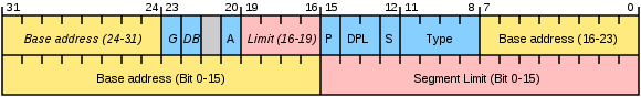
Please note that under the base 32 bits are allocated, and under the limit of only 20. How is it - you ask - is it impossible to create a segment whose size will be larger than a megabyte? Can. To do this, use a simple trick. If the G bit is set to one, then the limit is considered not in bytes, but in blocks of 4 KB. It should be noted that the limit contains the size of the segment minus one in units of granularity, i.e. if the limit is 0, then the segment has a size of 1 byte or 4 KB. In addition, as you can see, the descriptor includes several more fields. Their detailed description can be found, for example, here .
As mentioned, the descriptors are stored in special tables. There may be several tables, but in any case GDT is required in the memory - a global table of descriptors. It is one for the entire operating system. In turn, each task, that is, a process, can have zero, one, or several LDT — local descriptor tables. The address and size of the GDT is stored in the GDTR register , the current LDT is in the LDTR register. For now, LDT is not needed. In addition, there are still IDT - tables of interrupt descriptors, but we will postpone their consideration until the next release.
To select a descriptor from a table, a data structure called a selector is used. Here is what it looks like:

The selector contains a bit that indicates in which table to search for a descriptor, local or global (L / G) and the actual descriptor number (descriptor number). In addition, the selector has an RPL field, but it does not interest us yet.
So let's get down to business!
Now we will explain the code a little.
In the rows:
The A20 address line is unlocked. What does it mean? Recall that in real mode you can address 1 MB of memory in the
After loading the address and the limit of the global table of descriptors in the GDTR register, there is a general ban on interruptions. This is explained by the fact that all interrupt handlers work in real mode, and problems with addressing will start in protected mode. So while strictly forbid interrupts.
Enabling protected mode is done by setting the low-order bit of the
Here, the prefix is used to convert the bitness of the operand
To run the program, you need to do the manipulations that completely coincide with those described in the first article . There you will find a list of references in case you want to learn more about protected mode.
We didn’t have enough imagination for anything that demonstrates the real possibilities of protected mode, so again we output “Hello, World!”, But using direct access to the video memory. To make something beautiful, it would be convenient to use interrupts. How to use them in protected mode will be the next article in our cycle. And the second article ends here. We will be glad to see your feedback and wishes.
Let's remember for a moment our program from the previous issue. It was launched instead of the operating system and displayed the message “Hello world”. The program was written in a 16-bit assembler and worked in the so-called real mode . As you probably know, when addressing in real mode, the physical address is formed using a segment and offset and has a dimension of 20 bits. Simple math tells us that this way you can access the entire megabyte of RAM.
The small amount of available memory is not the only problem in real mode. Imagine a situation where the operating system and several application programs are in memory at the same time. In real mode, nothing prevents any of the application programs from contacting an address belonging to another program or even an operating system. Thus, an error in one program can lead to the collapse of the entire system.
To solve these two problems, Intel at one time developed a new, much more complicated way of addressing RAM. More precisely, Intel developed even several ways of addressing, and all of them are known under the collective name of protected mode .
')
So, addressing in protected mode can occur in one of three modes (sorry for tautology) - in segment, page and segment-page. In this issue, we will look at segment mode only.
In the segment mode in memory are allocated, oddly enough, segments. These segments are significantly different from the simple and familiar segments of the real mode. In this case, a segment is a continuous memory area, which is characterized by a base, a limit (that is, roughly speaking, size) and some additional attributes. The base is, roughly speaking, the physical address from which the segment begins (in fact, this is not a physical address, but the so-called linear address, but more on that later). It is important to note that, unlike the real mode segments, our segments can be of arbitrary size. The base, size and attributes of each segment are stored in the descriptor . The descriptors are stored in special tables, and selectors are used to select a specific descriptor from the table. Do not be alarmed by such a heap of new scary words, we will now sort everything out.
So, each time a memory is accessed, the processor takes a register (for example, CS), a selector, finds the desired descriptor in the table, extracts the segment start address from the descriptor, adds an offset to the start address and gets a linear address (note that and the physical address is different things, but at this stage it can be assumed that they are one and the same). In addition, the processor checks whether the received address is out of the segment boundary and whether segment attributes allow access to it at the moment. The scheme for calculating the linear address looks like this:
So, as we have already said, the base (base address), the size (segment limit) and any additional segment attributes are stored in the descriptor. Let's take a look at the descriptor scheme.
Please note that under the base 32 bits are allocated, and under the limit of only 20. How is it - you ask - is it impossible to create a segment whose size will be larger than a megabyte? Can. To do this, use a simple trick. If the G bit is set to one, then the limit is considered not in bytes, but in blocks of 4 KB. It should be noted that the limit contains the size of the segment minus one in units of granularity, i.e. if the limit is 0, then the segment has a size of 1 byte or 4 KB. In addition, as you can see, the descriptor includes several more fields. Their detailed description can be found, for example, here .
As mentioned, the descriptors are stored in special tables. There may be several tables, but in any case GDT is required in the memory - a global table of descriptors. It is one for the entire operating system. In turn, each task, that is, a process, can have zero, one, or several LDT — local descriptor tables. The address and size of the GDT is stored in the GDTR register , the current LDT is in the LDTR register. For now, LDT is not needed. In addition, there are still IDT - tables of interrupt descriptors, but we will postpone their consideration until the next release.
To select a descriptor from a table, a data structure called a selector is used. Here is what it looks like:
The selector contains a bit that indicates in which table to search for a descriptor, local or global (L / G) and the actual descriptor number (descriptor number). In addition, the selector has an RPL field, but it does not interest us yet.
So let's get down to business!
;16- ,
use16
org 0x7c00
start :
jmp 0x0000 : entry ; CS=0, IP=0x7c00
entry :
mov ax , cs
mov ds , ax

;
mov ax , 0x0003
int 0x10

; A20
in al , 0x92
or al , 2
out 0x92 , al

; GDT GDTR
lgdt [ gdtr ]
;
cli
;
in al , 0x70
or al , 0x80
out 0x70 , al

;
mov eax , cr0
or al , 1
mov cr0 , eax

; CS:EIP
O32 jmp 00001000b : pm_entry

;32-
use32
;
pm_entry :
; ( SS)
mov ax , cs
mov ds , ax
mov es , ax

mov edi , 0xB8000 ; 0x3
mov esi , msg ;
cld
. loop ;
lodsb ;
test al , al ; 0
jz . exit ;
stosb ;
mov al , 7 ;
stosb
jmp . loop
. exit

jmp $ ;

msg :
db 'Hello World!' , 0

; .
; !
gdt :
db 0x00 , 0x00 , 0x00 , 0x00 , 0x00 , 0x00 , 0x00 , 0x00
db 0xFF , 0xFF , 0x00 , 0x00 , 0x00 , 10011010b , 11001111b , 0x00
gdt_size equ $ - gdt

;, GDTR
gdtr :
dw gdt_size - 1
dd gdt

finish :
times 0x1FE - finish + start db 0
db 0x55 , 0xAA ;
Now we will explain the code a little.
In the rows:
in al , 0x92 <br/>
or al , 2 <br/>
out 0x92 , al
The A20 address line is unlocked. What does it mean? Recall that in real mode you can address 1 MB of memory in the
: format (20 bits per address). However, if you contact, for example, FFFF:FFFF , you can jump a little higher than this bar, and the resulting address will be 21 bits long. In processors up to 80286, the older one (the twentieth, if counted from zero) was dropped, and therefore, for compatibility with old programs, they introduced blocking of the address line A20. Currently, all operating systems operate in a secure mode, and therefore for the needs of addressing it is necessary to unblock this bit as soon as possible. So it goes.After loading the address and the limit of the global table of descriptors in the GDTR register, there is a general ban on interruptions. This is explained by the fact that all interrupt handlers work in real mode, and problems with addressing will start in protected mode. So while strictly forbid interrupts.
Enabling protected mode is done by setting the low-order bit of the
CR0 register. Immediately after the transition to the protected mode, a certain uncertainty arises: in CS:EIP you need to set the entry point to the protected mode in the : format : , and we still have vestiges of the real mode there. Therefore we execute the following instruction:O32 jmp 00001000b : pm_entryHere, the prefix is used to convert the bitness of the operand
O32 , which allows you to make a far unconditional transition with 32-bit offset. Hurray, we can finally take advantage of the charms of protected mode!To run the program, you need to do the manipulations that completely coincide with those described in the first article . There you will find a list of references in case you want to learn more about protected mode.
We didn’t have enough imagination for anything that demonstrates the real possibilities of protected mode, so again we output “Hello, World!”, But using direct access to the video memory. To make something beautiful, it would be convenient to use interrupts. How to use them in protected mode will be the next article in our cycle. And the second article ends here. We will be glad to see your feedback and wishes.
Source: https://habr.com/ru/post/104988/
All Articles