Device Link Control ("pingovalka")
The article describes its own development - a device for monitoring the state of the link and equipment. The idea of the device is not new, the essence lies in the periodic sending of ICMP requests to the specified addresses and the subsequent reaction in case of not receiving a response.
The device is designed to control IP connections with devices on the network and can be used to monitor the availability of a network node or outgoing connection outside the network.
')
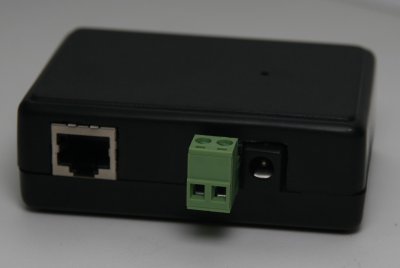
The device is equipped with an interface for connecting to an Ethernet network, a relay output with a normally closed contact for connecting power supply circuits or control circuits of the monitored equipment, as well as a power connector of the device itself.
The relay output allows switching circuits with voltages up to 250 volts and currents up to 10 amperes.
Power supply device - 5V. Current consumption up to 100 mA.
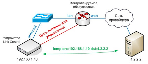
In this scheme, the Link Control device connects to the local segment of the monitored equipment and checks the availability of a specific node in the external segment. The device controls the channel between the router and the provider’s network and in case the connection is lost, Link Control will reload the router along the power circuit.
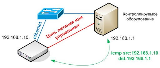
In this scheme, the availability of a specific node in the network is controlled, and in case of lack of connectivity with the equipment, the Link Control device will restart the node via power or reset circuits.
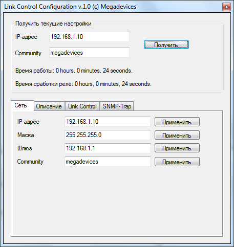
The device is configured using the Link Control Configuration software. To configure the device, the SNMP protocol is used, to connect to the device, you must specify the IP address of the device and the Community String used.
To restore the initial settings, press the Reset button located inside the device for 5 seconds, the hole for access to the button is located on the top cover of the device.
To change the settings in the corresponding fields of the configurator, you must specify the current address and community, after which the program will receive all the current settings from the device or will give an error message if one of the parameters is entered incorrectly.
Device settings are defined in the four tabs of the program, the current network settings are configured in the Network tab, as well as the Community String parameter. Changes are sent to the device after clicking the "Apply" button opposite the corresponding field.
When changing the address of the device or community, you need to reconnect to the device and get the current settings.
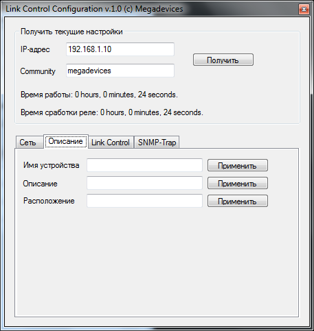
In the “Description” tab you can configure the name of the monitored device, its brief description and geographical location, all of these fields are standard for the SNMP protocol.
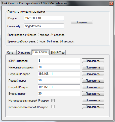
In the “Link Control” tab, the device behavior is configured when monitoring equipment using the ICMP protocol.
The ICMP interval field determines how often ICMP requests are sent to specified IP addresses; the field value is specified in seconds.
The Waiting Interval field defines the time the device waits between triggering a relay output and starting the sending of ICMP requests. It can be adjusted to adapt to the operating system boot time in the monitored nodes.
The First IP Address field defines the primary address to which ICMP requests will be sent.
The First Threshold field determines how many unconfirmed requests will be sent before the relay output is triggered.
The Second IP address field defines the secondary control address to which requests will be sent when the first threshold of unconfirmed packets is reached.
The Second threshold field determines how many unconfirmed requests will be sent before the relay output is triggered.
The Use First IP Address and Use Second IP Address fields determine whether the device will send requests to the specified addresses.
The second address can only be used if the first address is used. Receiving a response to a request for any of the addresses resets the threshold values of both addresses.
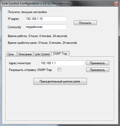
The SNMP-Trap tab defines the parameters for sending notifications when a relay is triggered. The Monitor Address field defines the IP address of the control station to which notifications of the relay output are transmitted. In SNMP-Trap, the parameters defined in the Description tab are transmitted.
Optionally, you can enable or disable the sending of SNMP-Trap notifications when a relay is triggered.
The “SNMP-Trap” tab also has a button that allows you to forcibly enable the relay output for testing.
general description
The device is designed to control IP connections with devices on the network and can be used to monitor the availability of a network node or outgoing connection outside the network.
')
The device is equipped with an interface for connecting to an Ethernet network, a relay output with a normally closed contact for connecting power supply circuits or control circuits of the monitored equipment, as well as a power connector of the device itself.
The relay output allows switching circuits with voltages up to 250 volts and currents up to 10 amperes.
Power supply device - 5V. Current consumption up to 100 mA.
Typical device wiring diagrams
In this scheme, the Link Control device connects to the local segment of the monitored equipment and checks the availability of a specific node in the external segment. The device controls the channel between the router and the provider’s network and in case the connection is lost, Link Control will reload the router along the power circuit.
In this scheme, the availability of a specific node in the network is controlled, and in case of lack of connectivity with the equipment, the Link Control device will restart the node via power or reset circuits.
Device configuration
The device is configured using the Link Control Configuration software. To configure the device, the SNMP protocol is used, to connect to the device, you must specify the IP address of the device and the Community String used.
To restore the initial settings, press the Reset button located inside the device for 5 seconds, the hole for access to the button is located on the top cover of the device.
To change the settings in the corresponding fields of the configurator, you must specify the current address and community, after which the program will receive all the current settings from the device or will give an error message if one of the parameters is entered incorrectly.
Device settings are defined in the four tabs of the program, the current network settings are configured in the Network tab, as well as the Community String parameter. Changes are sent to the device after clicking the "Apply" button opposite the corresponding field.
When changing the address of the device or community, you need to reconnect to the device and get the current settings.
In the “Description” tab you can configure the name of the monitored device, its brief description and geographical location, all of these fields are standard for the SNMP protocol.
In the “Link Control” tab, the device behavior is configured when monitoring equipment using the ICMP protocol.
The ICMP interval field determines how often ICMP requests are sent to specified IP addresses; the field value is specified in seconds.
The Waiting Interval field defines the time the device waits between triggering a relay output and starting the sending of ICMP requests. It can be adjusted to adapt to the operating system boot time in the monitored nodes.
The First IP Address field defines the primary address to which ICMP requests will be sent.
The First Threshold field determines how many unconfirmed requests will be sent before the relay output is triggered.
The Second IP address field defines the secondary control address to which requests will be sent when the first threshold of unconfirmed packets is reached.
The Second threshold field determines how many unconfirmed requests will be sent before the relay output is triggered.
The Use First IP Address and Use Second IP Address fields determine whether the device will send requests to the specified addresses.
The second address can only be used if the first address is used. Receiving a response to a request for any of the addresses resets the threshold values of both addresses.
The SNMP-Trap tab defines the parameters for sending notifications when a relay is triggered. The Monitor Address field defines the IP address of the control station to which notifications of the relay output are transmitted. In SNMP-Trap, the parameters defined in the Description tab are transmitted.
Optionally, you can enable or disable the sending of SNMP-Trap notifications when a relay is triggered.
The “SNMP-Trap” tab also has a button that allows you to forcibly enable the relay output for testing.
Source: https://habr.com/ru/post/103206/
All Articles