1-wire at the enterprise, physical level

The introductory article of this series can be found here.
Formulation of the problem
Let's start with the fact that I got a job in an organization engaged in the production of medical components. This organization works with a large amount of biological material: serum, viruses, solutions and other ... In order to store the original components and the products produced, it is necessary to withstand strict temperature and humidity conditions, otherwise it will all deteriorate, so the company uses a large number of refrigerators, freezers and cold rooms / warehouses.
To control the temperature, the following approach is used: a thermometer hangs at each control refrigerator (as a rule, an ordinary Chinese home thermometer); and once every two hours, a special responsible person in each department bypasses and records in a special journal the current temperature in the refrigerators belonging to that department; if it is not working time (evening, weekend), then this tour is performed by the duty officer on the hull.
')
In order to roughly imagine the scale of this action, I will explain what the organization is: these are two of their own buildings of 4 and 7 floors, geographically separated by about 20-25 km and two leased non-adjacent floors in the third building. There are approximately 200, 100 and 30 units of refrigeration equipment in these premises, respectively.
The chief engineer of the organization thought and decided that it was not rational in our age of information technology and total automation, and ordered the whole business to be automated. More specifically: I wanted to see in some form on the screen the current temperature of all objects, and also to somehow signal when going beyond the specified boundary values, also to be able to archive and view archived data for different periods of time.
Projection
After a brief discussion, it was decided to use Dallas Semiconductor solutions based on the 1-Wire microlan bus \ protocol.
Based on what was made such a decision?
- Firstly, the company DS has a wonderful compact digital sensors DS18b20.
- Secondly, for the same tire, there are a number of other sensors and devices (in particular, humidity sensors, humidity control is also relevant), which implies the possibility of a good further expansion.
- Thirdly, this is a relatively small number of wires that will have to be pulled in all housings.
- Fourth, a fairly large diameter network segment - up to 300 meters, and the ability to change the network configuration on the fly.
Stage one. Physical level
In this section I will talk about the organization of the actual physical SCS, what rake we stepped on and how, and why did it happen that in different buildings we have a little different physics.
A central cable was stretched from the top floor to the basement along a low-current riser and, on each floor, from the left wing to the opposite edge of the right wing was thrown over the cable, since this is a common bus, then all the conductors are connected in parallel and in any place; later, branches from different rooms were connected to this tree-like frame of cables.
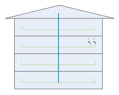
As a cable, a 4-core twisted pair category 5e was used, in rooms next to refrigerators we put outlets like RJ-11 \ RJ-12 (standard telephone sockets 4/6 pins), we hung up our sensor in the fridge (it is a piece of flat telephone cable with a pacifier on one side and a DS18B20 soldered chip on the other). Photo .
Of the four wires of the cable, three are used: ground, power / data, and an additional power core. The fourth vein remained in reserve for the future.
So on the first building (where the largest number of objects) we all laid and connected, put sockets in each room, connected sensors and ...
and it turned out that all this together does not work.
Each floor worked perfectly separately, but not all together. Began to understand, it turned out that:
- First: on parasitic power (this is when external sensor power is not connected, but only two conductors are used), then no more than 10-15 sensors can work simultaneously. They do not have enough power and time to charge the internal capacitor, the decision on a slower survey, we discarded.
- Secondly: even if there is an external power supply, no more than 50 sensors can work on the same bus, they looked with an oscilloscope - because of the long and highly branched lines, the fronts collapse, reflections arise, and confusion results.
Here it is necessary to retreat a little and tell about how we checked the whole thing.
Used a laptop with various adapters:
adapter1

adapter2
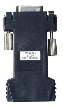
adapter3

depending on the adapter, the maximum number of working sensors on the line also changed.
Adapter3 showed the best. (which by the way is not at all an official PC adapter from DS, but our domestic fake link collected on a PIC controller)
further we decided: it is to divide our network into segments by floor using a DS2409 microcircuit, it is also a 1-wire microcircuit that works as a switch or multiplexer, it has one input and two outputs, it has its own address and understands the commands to connect the input with the output1 or with exit2.
It turned out something like this:
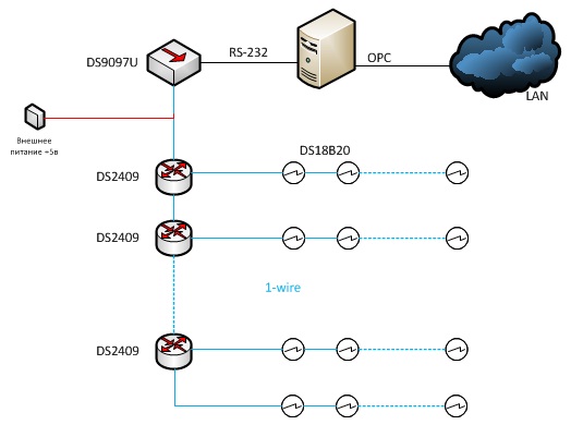
Each branch is a separate floor, on the floor in the attic, an adapter connected to the server's serial port, on which a special program is spinning that gives commands to switch branches and sequentially polls all sensors in each branch.
And so are three buildings.
To date, we have three corps work and are polled according to this scheme. If you have questions, I will be glad to answer and add to this note.
On the applied programs and on the software part separately, in the next article. If of course it is interesting to someone;)
Related Links
Dallas Semiconductor they are Maxim
Elin. a lot of useful information
Well, thanks to Siemens for the picture :)
Source: https://habr.com/ru/post/102756/
All Articles