Programming for Nintendo DS. Simplest game
In this article we will consider working with tile graphics, interrupts, touch screen and keyboard. Based on this, we will write to everyone from childhood a well-known game - “tag”.
For a start, let's take a closer look at how to work with the DS video controller.
Almost all video modes use a “multi-layered” structure of display organization, that is, we can simultaneously display up to 4 plans (background). I don’t know what term is better to use, let it be a “plan” - “background”.
In total there are 6 types of backgrounds:
')
As already mentioned, both Nintendo DS graphics cores share common video memory (656KB). It is divided into 9 banks of various sizes and purposes, named in Latin letters from A to I. Here is the complete list. In order for the video controller to use these banks, we must otprazit ("zamapit") them in a special area of the address space, starting with 0x06000000.
More detailed about the organization of video memory and the appointment of various banks can be read here .
In the game we will use the zero graphic mode of the video controller (MODE_0_2D), which has 4 tile plans. On the lower screen (by default, an additional core) in one of them the game will actually take place (moving the chips), and the other is applicable to display the splash image. The upper screen (main core) is used simply to display textual information.
Now we delve a little into the organization of video memory in the mode of tile plans. The picture on the screen in this mode is formed on the basis of the so-called tile map, in which numbers of tiles are written, which should be displayed in squares of 8x8 pixels on the image. The tiles themselves are stored in a separate memory area. From what addresses the video controller will display the map and tiles are determined by the control register (Control Register - CR). Each of the 8 plans (4 on the main core and 4 on the additional one) has its own register. In our case, you need to initialize 3 of them: SUB_BG0_CR, SUB_BG1_CR and BG0_CR - one for each of the used plans.
There is a little trick. The fact is that the control registers are 16 bit, and in them you need to store both the address of the map and the address of tiles and other parameters. Because of this, 5 bits are allocated for addresses. Thus, tiles can be stored at 32 base addresses with an offset of 16K, and maps at 32 addresses with a displacement of 2K.
Given that they are stored in one memory bank, we have the following picture:
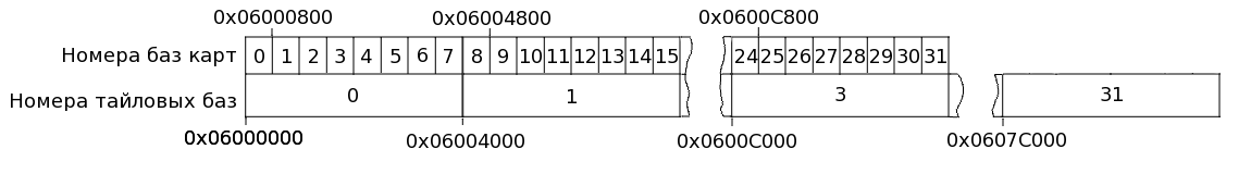
We need 2 tile maps for the bottom screen. They will be located at base addresses 0 and 1. We will also need 2 sets of tiles themselves. The zero base address of the tiles intersects with the memory used by the cards, so we will not use it. From the base address No. 1 we will place tiles of chips. They occupy 36 KB, so the base addresses 2, 3 and 4, we also will not use. Next, from address 5 we will place a set of tiles for the start screen saver.
For the upper screen, we use a tile map from the base address 0, and the tiles themselves that will contain the Russian font will be placed from address 1. The control register for the text will set libNDS when the console is initialized.
Now we initialize our control registers to use 16 color tiles (BG_COLOR16):
In fact, it was possible to save a fair amount of video memory (32KB), if you place the tiles and maps at other base addresses. However, in our case, such optimization is not required, since free memory is more than enough.
Now we translate the base address numbers into absolute addresses of the video memory so that you can work with it directly:
Then we copy the data of our tiles into the video memory:
And immediately fill in the zero plan of the lower screen with screen saver tiles:
Each word in the tile map except the tile number contains information about the palette and reflections along the axes. In order to use the first palette, we set 12 bits to 1 for each map element.
If we paint the tile map element bit by bit, we will see the following:
Initialize the libNDS console:
In the program we use the font created by ClusterM for PAlib in CP1251 encoding. Unfortunately, in the current version of the library, when attempting to switch to Unicode, they broke the support for outputting characters in the upper half of ASCII, so you have to do without the Russian text. Although of course it can be displayed directly by writing character codes to a tile card.
All tiles are created by converting from BMP using the grit program.
To read the state of the keys without using libNDS, we would have to use not only the registers of the ARM9 processor, but also the ARM7. Fortunately, the creators of the library will be able to disregard this fact. We simply use the scanKeys () function to update the status of the click information. And keysHeld () to determine which key is pressed, or pressing the touch screen. What exactly is pressed is determined according to the bits of the value returned by the function:
So we just do a loop:
And then, depending on the fact that in the held variable we perform the necessary actions.
If the KEY_TOUCH bit is set, then a touchscreen click is detected and we can read the coordinates of the stylus using the touchRead function. It returns a touchPosition structure in which we are interested in the px and py fields, which contain the coordinates of the pixel that the stylus points to:
For the normal operation of most programs interacting with the user (our program is not an exception), control of time intervals is required, which is usually provided by interrupts from timers. There are three registers for working with interrupts:
The Interrupt Master Enable Register provides the ability to enable and disable all interrupt handlers.
The Interrupt Enable Register allows you to enable or disable individual interrupts. Each bit of the register is responsible for a specific interrupt:
The Interrupt Flags Register is set by hardware when an interrupt occurs. It contains the interrupt bit mask.
We will not work with interruptions directly, but as usual, we will use the services of libnds.
First, we set the interrupt handler for the “vertical beam reversal”. This interrupt will be called when the screen is finished drawing. In the handler for this interrupt, we will display a picture to avoid flickering and tearing of the image:
Next, set one of the timers to the desired frequency and set an interrupt handler on it. The libNDS library for this purpose provides a very convenient timerStart function. It is enough for us to call this function with the necessary divider, frequency and pointer to the interrupt handler, in order to complete the initialization of the timer and interrupt.
Finally, consider another function provided by libnds library - swiWaitForVBlank. It stops the ARM9 processor before the arrival of a vertical ray traverse interruption.
Using all the above, you can already write a simple game. Here you can take the source code of the game "tag", and here the executable file.
Screenshot:

For a start, let's take a closer look at how to work with the DS video controller.
Video Controller Initialization
Almost all video modes use a “multi-layered” structure of display organization, that is, we can simultaneously display up to 4 plans (background). I don’t know what term is better to use, let it be a “plan” - “background”.
In total there are 6 types of backgrounds:
- framebuffer - The simplest type of background. Each word (16bit) in video memory is displayed as a pixel on the screen. (Used in the last example);
- 3D - The image on the screen is formed by OpenGL-like teams;
- text - The text background (also known as tayl) is divided into blocks of 8x8 pixels, each of which displays one of the tiles;
- rotation - Tile plan with the possibility of rotation and scaling;
- extended rotation - Same as framebuffer, but also allows you to display a color depth of 8 bits per pixel, and also supports scrolling, scaling, and rotation; in addition, it can use alpha bits;
- large bitmap - Large 512x1024 or 1024x512 images with 8 bits per pixel.
')
As already mentioned, both Nintendo DS graphics cores share common video memory (656KB). It is divided into 9 banks of various sizes and purposes, named in Latin letters from A to I. Here is the complete list. In order for the video controller to use these banks, we must otprazit ("zamapit") them in a special area of the address space, starting with 0x06000000.
More detailed about the organization of video memory and the appointment of various banks can be read here .
In the game we will use the zero graphic mode of the video controller (MODE_0_2D), which has 4 tile plans. On the lower screen (by default, an additional core) in one of them the game will actually take place (moving the chips), and the other is applicable to display the splash image. The upper screen (main core) is used simply to display textual information.
videoSetMode(MODE_0_2D | DISPLAY_BG0_ACTIVE); //
videoSetModeSub(MODE_0_2D | DISPLAY_BG1_ACTIVE | DISPLAY_BG0_ACTIVE); //

* This source code was highlighted with Source Code Highlighter .
Now we delve a little into the organization of video memory in the mode of tile plans. The picture on the screen in this mode is formed on the basis of the so-called tile map, in which numbers of tiles are written, which should be displayed in squares of 8x8 pixels on the image. The tiles themselves are stored in a separate memory area. From what addresses the video controller will display the map and tiles are determined by the control register (Control Register - CR). Each of the 8 plans (4 on the main core and 4 on the additional one) has its own register. In our case, you need to initialize 3 of them: SUB_BG0_CR, SUB_BG1_CR and BG0_CR - one for each of the used plans.
There is a little trick. The fact is that the control registers are 16 bit, and in them you need to store both the address of the map and the address of tiles and other parameters. Because of this, 5 bits are allocated for addresses. Thus, tiles can be stored at 32 base addresses with an offset of 16K, and maps at 32 addresses with a displacement of 2K.
Given that they are stored in one memory bank, we have the following picture:
We need 2 tile maps for the bottom screen. They will be located at base addresses 0 and 1. We will also need 2 sets of tiles themselves. The zero base address of the tiles intersects with the memory used by the cards, so we will not use it. From the base address No. 1 we will place tiles of chips. They occupy 36 KB, so the base addresses 2, 3 and 4, we also will not use. Next, from address 5 we will place a set of tiles for the start screen saver.
For the upper screen, we use a tile map from the base address 0, and the tiles themselves that will contain the Russian font will be placed from address 1. The control register for the text will set libNDS when the console is initialized.
Now we initialize our control registers to use 16 color tiles (BG_COLOR16):
int tile_base = 1;
int map_base = 0;
int tile_base_s = 5;
int map_base_s = 1;
int char_base = 1;
int scr_base = 0;
REG_BG0CNT_SUB = BG_COLOR_16 | BG_TILE_BASE(tile_base_s) | BG_MAP_BASE(map_base_s); //
REG_BG1CNT_SUB = BG_COLOR_16 | BG_TILE_BASE(tile_base) | BG_MAP_BASE(map_base); //

* This source code was highlighted with Source Code Highlighter .
In fact, it was possible to save a fair amount of video memory (32KB), if you place the tiles and maps at other base addresses. However, in our case, such optimization is not required, since free memory is more than enough.
Now we translate the base address numbers into absolute addresses of the video memory so that you can work with it directly:
u16* sub_tile = (u16*)BG_TILE_RAM_SUB(tile_base);
u16* sub_map = (u16*)BG_MAP_RAM_SUB(map_base);
u16* sub_tile0 = (u16*)BG_TILE_RAM_SUB(tile_base_s);
u16* sub_map0 = (u16*)BG_MAP_RAM_SUB(map_base_s);
u16* tile_char = (u16*)BG_TILE_RAM(char_base);
u16* map_char = (u16*)BG_MAP_RAM(scr_base);

* This source code was highlighted with Source Code Highlighter .
Then we copy the data of our tiles into the video memory:
memcpy(( void *)sub_tile, (u8*)tilesTiles, 192*192/2); //
for (i=0; i < 16; ++i)
BG_PALETTE_SUB[i] = tilesPal[i]; //
memcpy(( void *)sub_tile0, (u8*)startTiles, 256*192/2); //
for (i=0; i < 16; ++i)
BG_PALETTE_SUB[i+16] = startPal[i]; //

* This source code was highlighted with Source Code Highlighter .
And immediately fill in the zero plan of the lower screen with screen saver tiles:
for (i=0; i< 24*32; i++) //
sub_map0[i] = (u16)(i)|0x1000;

* This source code was highlighted with Source Code Highlighter .
Each word in the tile map except the tile number contains information about the palette and reflections along the axes. In order to use the first palette, we set 12 bits to 1 for each map element.
If we paint the tile map element bit by bit, we will see the following:
| Bits | 15 | 14 | 13 | 12 | eleven | ten | 9 | eight | 7 | 6 | five | four | 3 | 2 | one | 0 |
|---|---|---|---|---|---|---|---|---|---|---|---|---|---|---|---|---|
| Purpose | Palette | Vetrik.otr. | Horiz.otr. | Tile number | ||||||||||||
Initialize the libNDS console:
PrintConsole *console = consoleInit(NULL, 0, BgType_Text4bpp, BgSize_T_256x256, scr_base, char_base, true , true );
ConsoleFont font;
font.gfx = (u16*)pa_text2Tiles; //
font.pal = (u16*)pa_text2Pal; //
font.numChars = 256; //
font.numColors = pa_text2PalLen/2;
font.bpp = 4;
font.asciiOffset = 0;
font.convertSingleColor = false ;
consoleSetFont(console, &font);

* This source code was highlighted with Source Code Highlighter .
In the program we use the font created by ClusterM for PAlib in CP1251 encoding. Unfortunately, in the current version of the library, when attempting to switch to Unicode, they broke the support for outputting characters in the upper half of ASCII, so you have to do without the Russian text. Although of course it can be displayed directly by writing character codes to a tile card.
All tiles are created by converting from BMP using the grit program.
Keyboard and touchscreen
To read the state of the keys without using libNDS, we would have to use not only the registers of the ARM9 processor, but also the ARM7. Fortunately, the creators of the library will be able to disregard this fact. We simply use the scanKeys () function to update the status of the click information. And keysHeld () to determine which key is pressed, or pressing the touch screen. What exactly is pressed is determined according to the bits of the value returned by the function:
| Key define | Mask Bit | Associated Input |
|---|---|---|
| KEY_A | 1 << 0 | A button |
| KEY_B | 1 << 1 | Button b |
| KEY_SELECT | 1 << 2 | Select button |
| KEY_START | 1 << 3 | Start button |
| KEY_RIGHT | 1 << 4 | Button to the right |
| KEY_LEFT | 1 << 5 | Button left |
| KEY_UP | 1 << 6 | Button up |
| KEY_DOWN | 1 << 7 | Button down |
| KEY_R | 1 << 8 | R button |
| KEY_L | 1 << 9 | L button |
| KEY_X | 1 << 10 | X button |
| KEY_Y | 1 << 11 | Y button |
| KEY_TOUCH | 1 << 12 | Touching the screen |
| KEY_LID | 1 << 13 | Lid closed |
So we just do a loop:
scanKeys();
held = keysHeld();
* This source code was highlighted with Source Code Highlighter .
And then, depending on the fact that in the held variable we perform the necessary actions.
If the KEY_TOUCH bit is set, then a touchscreen click is detected and we can read the coordinates of the stylus using the touchRead function. It returns a touchPosition structure in which we are interested in the px and py fields, which contain the coordinates of the pixel that the stylus points to:
if (held&KEY_TOUCH){ //
touchRead(&touchXY);
...
}
* This source code was highlighted with Source Code Highlighter .
Interruptions
For the normal operation of most programs interacting with the user (our program is not an exception), control of time intervals is required, which is usually provided by interrupts from timers. There are three registers for working with interrupts:
| Name | Address | The size | Description |
|---|---|---|---|
| REG_IME | 0x04000208 | 16 bits | Main interrupt enable register |
| REG_IE | 0x04000210 | 32 bits | Interrupt Enable Register |
| REG_IF | 0x04000214 | 32 bits | Interrupt Flag Register |
The Interrupt Master Enable Register provides the ability to enable and disable all interrupt handlers.
The Interrupt Enable Register allows you to enable or disable individual interrupts. Each bit of the register is responsible for a specific interrupt:
| Bit | Libnds names | Description |
|---|---|---|
| 0 | IRQ_VBLANK | vertical ray traverse |
| one | IRQ_HBLANK | horizontal retrace |
| 2 | IRQ_YTRIGGER | scanned line REG_VCOUNT |
| 3 | IRQ_TIMER0 | Timer 0 tripped |
| four | IRQ_TIMER1 | Timer 1 triggered |
| five | IRQ_TIMER2 | Timer 2 has triggered. |
| 6 | IRQ_TIMER3 | Timer 3 tripped |
| 7 | IRQ_NETWORK | ? |
| eight | IRQ_DMA0 | DMA 0 |
| 9 | IRQ_DMA1 | DMA 1 |
| ten | IRQ_DMA2 | DMA 2 |
| eleven | IRQ_DMA3 | DMA 3 |
| 12 | IRQ_KEYS | Key pressed |
| 13 | IRQ_CART | GBA cartridge removed |
| sixteen | ARM7 triggered IPC interrupt | |
| 17 | Input FIFO is not empty | |
| 18 | Output FIFO is not empty | |
| nineteen | IRQ_CARD | DS card data completed |
| 20 | IRQ_CARD_LINE | DS card interrupt 3 |
| 21 | GFX FIFO interrupt |
The Interrupt Flags Register is set by hardware when an interrupt occurs. It contains the interrupt bit mask.
We will not work with interruptions directly, but as usual, we will use the services of libnds.
First, we set the interrupt handler for the “vertical beam reversal”. This interrupt will be called when the screen is finished drawing. In the handler for this interrupt, we will display a picture to avoid flickering and tearing of the image:
void IRQ_vblank( void ){ //
... ...
}
...
irqSet(IRQ_VBLANK, IRQ_vblank); // .

* This source code was highlighted with Source Code Highlighter .
Next, set one of the timers to the desired frequency and set an interrupt handler on it. The libNDS library for this purpose provides a very convenient timerStart function. It is enough for us to call this function with the necessary divider, frequency and pointer to the interrupt handler, in order to complete the initialization of the timer and interrupt.
void timer0_function( void ){
... ...
}
...
timerStart(0, ClockDivider_256, TIMER_FREQ_256(1000), timer0_function); // 256 1000

* This source code was highlighted with Source Code Highlighter .
Finally, consider another function provided by libnds library - swiWaitForVBlank. It stops the ARM9 processor before the arrival of a vertical ray traverse interruption.
Using all the above, you can already write a simple game. Here you can take the source code of the game "tag", and here the executable file.
Screenshot:
Source: https://habr.com/ru/post/102679/
All Articles