Setting up a routing for a home multihomed server
Now having multiple connections to the Internet on one, including the home server, is not uncommon. City lokalki, ADSL, 3G modems ... Add home local and external virtual networks (VPNs) to this network, and we get a core mix of interfaces between which you need to route traffic, balance traffic between different channels to the Internet (when they are), and switch from non-working channels to workers (when they fall off).
Judging by the posts in the internet, most people who are confronted with this situation, very poorly imagine how it is configured. It should be noted that, in linux, routing management is very complicated and confusing - a consequence of evolutionary development and support (partial) compatibility. I want to describe the principles of setting up routing for multihomed servers on a specific, rather complicated example: on the server there are three physical network interfaces (one to the home LAN and two to the ADSL modems), two ADSL connections (ADSL modems in the bridge mode, so pppd raises the same server) to different providers (one with a static IP, the second with a dynamic one), plus a VPN to the company's server - a total of six interfaces.
The topic is quite complicated, so to understand the material, you will need at least a minimal understanding of the routing operation (what default route and gateway are), firewall (packet marking, connection tracking, connection between different tables and firewall chains and routing), pppd (ip-up / ip-down) and IP and TCP protocols.
So, we have three network interfaces:
')
To configure routing earlier (and even now - in simple cases) the route command was used. You can forget about it - such settings are made only via the ip command (from the iproute2 package), and using ip and route at the same time will bring nothing but trouble. At the time of the route command, the routing table was one. Now there are several routing tables (and one of them is main — the same one that the route command works with). These tables are listed in / etc / iproute2 / rt_tables:
You can view their contents with the command ip route list table <table name> . There is nothing interesting in the local table - there are link-local rules for routing through the available interfaces; in the main table, the main routing rules; default table is empty; The unspec table (which can also be accessed as all ) displays all the routing rules from all existing tables.
To create new tables, you need to add their names to this file (more precisely, this is necessary only for referring to your tables by names — by numbers you can refer to them as well).
As soon as we had more than one routing table, we also needed a mechanism by which it was possible to select the routing table used — its name is the routing rules (RPDB, routing policy database) . The main advantage of this mechanism is the ability to choose routing not only based on the destination address (as the route command did and do ip route ... ), but also by other criteria (source address, interface, tos, fwmark, ...) fields. It works like this: you specify (via the ip rule ... command) any number of rules in the format “criteria-> routing table”. If for this packet the criteria in the routing rules match, and in the specified routing table there is a route for this packet (based on the destination address), then it will be executed; and if not, then we return to the routing rules and check other options. Here are the default routing rules:
The first column is priority; rules are viewed in order of increasing priority. These rules mean that you first look at the local table (where link-local routing rules are), then the main table (which you usually run through the route command) and where the default route is usually specified — that is, in this case, the execution of the routing rules stops, then (if the default route was not specified in main ) the default table (empty by default).
Here is a simple example of how all this farm can be used to process packets from the home localhost 192.168.2.100 address using separate routing rules other than the default routing (we give it access only to the first ADSL modem and to the Internet through the first provider ):
Now a little about the firewall. With it, it is also possible to influence the routing.
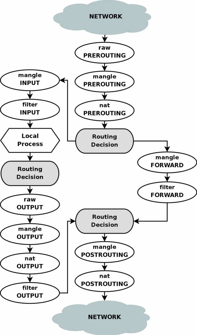
As you can see in the diagram, packages from, for example, local applications go through the “Routing Decision” stage twice. As far as I understand, the first time this happens at the time of the package creation is in order to determine the outgoing interface and outgoing IP for it (which can check the firewall rules, so they should already be known when the packet enters the firewall), plus rerouting for This package is calculated after the firewall chain MANGLE is executed, which could change any packet fields that could affect the routing of this package.
In our case, the easiest way to influence routing through a firewall is to change the fwmark field of the package in the MANGLE chain, and then use the routing rules to select the routing table based on the value of the fwmark field of the package (this requires creating several routing tables with different rules - for example, one table to write the default route through one provider, and the other through another provider).
The path to this end result is thorny in some places (thebugs of the features of pppd and openvpn do not allow us to relax) and therefore will be described below. In the meantime, let's see what we need to get.
To begin with, let's configure the simultaneous use of both providers, with load balancing in the ratio of 8 to 2 (according to the width of the channels). This method selects the routing for each individual destination address - i.e. if the connection initially went through the first provider, then all its packets will leave only through the first provider, and all subsequent connections to this address will leave for some time only through this provider. Balancing not by connection but by package is done differently, and will work only if we have several connections to one provider.
Because the kernel caches information about the connection of the destination addresses and the default routing selected for them, you may need to reset this cache (so that the kernel again, with a probability of 8 to 2, chooses the default routing for this destination address):
Because In some cases, we need to control through which of the external channels to send a packet, we will create for each channel a separate routing table with its own default route:
Now add the routing rules so that using the firewall by setting the desired fwmark values, we can select the desired routing table:
The value 0x4 / 0x4 (value / mask) means that the bits from the fxmark field will be taken using the 0x4 mask (i.e., only the third bit) which should match the value 0x4. Those. In fwmark, the third bit must be set in order for the rule for the vpn table to work, and the remaining bits do not matter. This approach allows the firewall to set several bits in the fwmark, thus specifying several "suitable" channels for this packet. The priority of these channels (if they are all available) is determined by the priority of the routing rules. If a channel is unavailable, then the corresponding routing table will still be viewed, but the default route will not appear in it, so a return to the following routing rules will occur and the next appropriate channel will be found.
All these commands haven’t affected anything yet - the fwmark firewall doesn’t set, then the routing rules for the isp1 , isp2 and vpn tables do not work, and the default routing is determined by the main table as before:
Now we can specify that access to the website with statistics and control panel of the second provider should go through the second ADSL:
If it is necessary that these rules work not only for packets outgoing from our server, but also for packets from home LAN, then all these rules must be added to the firewall not only in the OUTPUT chain, but also in the FORWARD chain.
All this will work fine while we are talking only about outgoing connections. But we have a server ... and there are incoming connections to the server. Let's say we have a website raised on static IP ssss (channel of the first provider). Now, if the admin of the second provider from the <ip_site_isp2> server wants to look (via lynx) on our website, it will not work! The fact is that he will send a request to our IP ssss (on which website) through the channel of our first provider, and our server will send the answer to this request through the channel of the second provider (and, accordingly, from the dddd address - we have, Of course, SNAT / MASQUERADE packets outgoing via the ppp0 , ppp1 and tun0 interfaces are configured - according to the firewall settings that we just made: send packets to the <ip_site_isp2> address via the second provider channel. The admin web browser that sent the request to the ssss address does not expect to receive a response from the dddd address, so it will not work.
To solve this problem, it is necessary to guarantee answers to incoming connections from the interface from which the packets were originally received. To do this, unfortunately, you have to use firewall connection tracking (conntrack) to set fwmark (connmark). Unfortunately - because conntrack is a big complex and buggy garbage, but there is no choice. It is done this way (these rules must be added to the firewall first, BEFORE the rules establishing a fwmark like the one described above):
Here we label incoming packets (more precisely, the connections to which they relate) according to the interfaces from which they came. Moreover, the fwmark value (more precisely, connmark) is chosen so that it corresponds to the routing table, through which you need to send responses to these packets (1,2,4 - for isp1, isp2 and vpn; 8 is not used in the routing rules fwmark, t .e. packets with this fwmark will be sent according to the usual routing in the main table - for packets from local networks, this is quite suitable).
This marking does not affect the routing of incoming packets, but this allows us to actually bind this marking to all packets of this connection, including outgoing packets. Next, for outgoing packets on the same connection (responses to incoming packets), we set the fwmark value to the same value as the incoming packets and which is bound to this connection (more precisely, copy the connmark value to fwmark). And if the result of outgoing packets is set to fwmark (not 0), then all subsequent fwmark installation rules for selecting the outgoing channel cannot be applied - this packet must be sent through the same interface through which the incoming packet came, so we stop (-j ACCEPT ).
So, the correct way to configure the firewall according to our problem statement is as follows:
Together with the settings of the rules and routing tables, we get exactly what we needed. It remains to figure out how to set these settings in the dynamics, given the fact that the channels may fall and rise.
Honestly, the article turned out and so rather big, so in addition to clutter it with your ip-up / down scripts, as I was going to, I will not now. If someone asks in the comments - add to the article later. And now I will briefly describe the main tasks and problems encountered in the implementation of the above settings.
Judging by the posts in the internet, most people who are confronted with this situation, very poorly imagine how it is configured. It should be noted that, in linux, routing management is very complicated and confusing - a consequence of evolutionary development and support (partial) compatibility. I want to describe the principles of setting up routing for multihomed servers on a specific, rather complicated example: on the server there are three physical network interfaces (one to the home LAN and two to the ADSL modems), two ADSL connections (ADSL modems in the bridge mode, so pppd raises the same server) to different providers (one with a static IP, the second with a dynamic one), plus a VPN to the company's server - a total of six interfaces.
The topic is quite complicated, so to understand the material, you will need at least a minimal understanding of the routing operation (what default route and gateway are), firewall (packet marking, connection tracking, connection between different tables and firewall chains and routing), pppd (ip-up / ip-down) and IP and TCP protocols.
General configuration and problem statement
So, we have three network interfaces:
- eth0 (192.168.0.2), connected to the first ADSL modem (192.168.0.1)
- eth1 (192.168.1.2), connected to the second ADSL modem (192.168.1.1)
- eth2 (192.168.2.1), is connected to the home LAN (192.168.2.x) and is the gateway to the Internet for this lokalki
- ppp0 (ssss), static IP through the first ADSL modem to the first provider (8Mbps)
- ppp1 (dddd), dynamic IP via second ADSL modem to the second provider (2Mbps)
- tun0 (vvvv), static IP over VPN to company server
- access from the server and home LAN to the Internet in the presence of any of the ADSL connections
- balancing traffic between ADSL connections if both are available, according to the width of the channels
- VPN should be raised through any ADSL connection, and if both are available, then through the first provider (wider channel)
- mail should be sent through the first provider (there is a static IP linked to my domain)
- access to the website with statistics and the control panel of the second provider must go through the second ADSL (the provider has closed access to his site outside)
')
A bit of theory
To configure routing earlier (and even now - in simple cases) the route command was used. You can forget about it - such settings are made only via the ip command (from the iproute2 package), and using ip and route at the same time will bring nothing but trouble. At the time of the route command, the routing table was one. Now there are several routing tables (and one of them is main — the same one that the route command works with). These tables are listed in / etc / iproute2 / rt_tables:
# cat /etc/iproute2/rt_tables # # reserved values # 255 local 254 main 253 default 0 unspec # # local # #1 inr.ruhep You can view their contents with the command ip route list table <table name> . There is nothing interesting in the local table - there are link-local rules for routing through the available interfaces; in the main table, the main routing rules; default table is empty; The unspec table (which can also be accessed as all ) displays all the routing rules from all existing tables.
To create new tables, you need to add their names to this file (more precisely, this is necessary only for referring to your tables by names — by numbers you can refer to them as well).
# route -n Kernel IP routing table Destination Gateway Genmask Flags Metric Ref Use Iface 127.0.0.0 127.0.0.1 255.0.0.0 UG 0 0 0 lo 192.168.0.0 0.0.0.0 255.255.255.0 U 0 0 0 eth0 192.168.1.0 0.0.0.0 255.255.255.0 U 0 0 0 eth1 192.168.2.0 0.0.0.0 255.255.255.0 U 0 0 0 eth2 # ip route list table main 127.0.0.0/8 via 127.0.0.1 dev lo scope link 192.168.0.0/24 dev eth0 proto kernel scope link src 192.168.0.2 192.168.1.0/24 dev eth1 proto kernel scope link src 192.168.1.2 192.168.2.0/24 dev eth2 proto kernel scope link src 192.168.2.1 As soon as we had more than one routing table, we also needed a mechanism by which it was possible to select the routing table used — its name is the routing rules (RPDB, routing policy database) . The main advantage of this mechanism is the ability to choose routing not only based on the destination address (as the route command did and do ip route ... ), but also by other criteria (source address, interface, tos, fwmark, ...) fields. It works like this: you specify (via the ip rule ... command) any number of rules in the format “criteria-> routing table”. If for this packet the criteria in the routing rules match, and in the specified routing table there is a route for this packet (based on the destination address), then it will be executed; and if not, then we return to the routing rules and check other options. Here are the default routing rules:
# ip rule list 0: from all lookup local 32766: from all lookup main 32767: from all lookup default The first column is priority; rules are viewed in order of increasing priority. These rules mean that you first look at the local table (where link-local routing rules are), then the main table (which you usually run through the route command) and where the default route is usually specified — that is, in this case, the execution of the routing rules stops, then (if the default route was not specified in main ) the default table (empty by default).
Here is a simple example of how all this farm can be used to process packets from the home localhost 192.168.2.100 address using separate routing rules other than the default routing (we give it access only to the first ADSL modem and to the Internet through the first provider ):
# echo '100 local100' >> /etc/iproute2/rt_tables # ip route add 192.168.0.0/24 dev eth0 table local100 # ip route add default via <__> dev ppp0 table local100 # ip rule add from 192.168.2.100 lookup local100 priority 5 # ip route list table local100 192.168.0.0/24 dev eth0 scope link default via <__> dev ppp0 # ip rule list 0: from all lookup local 5: from 192.168.2.100 lookup local100 32766: from all lookup main 32767: from all lookup default Now a little about the firewall. With it, it is also possible to influence the routing.
As you can see in the diagram, packages from, for example, local applications go through the “Routing Decision” stage twice. As far as I understand, the first time this happens at the time of the package creation is in order to determine the outgoing interface and outgoing IP for it (which can check the firewall rules, so they should already be known when the packet enters the firewall), plus rerouting for This package is calculated after the firewall chain MANGLE is executed, which could change any packet fields that could affect the routing of this package.
In our case, the easiest way to influence routing through a firewall is to change the fwmark field of the package in the MANGLE chain, and then use the routing rules to select the routing table based on the value of the fwmark field of the package (this requires creating several routing tables with different rules - for example, one table to write the default route through one provider, and the other through another provider).
Setting up the routing: the end result
The path to this end result is thorny in some places (the
Balancing between two providers
To begin with, let's configure the simultaneous use of both providers, with load balancing in the ratio of 8 to 2 (according to the width of the channels). This method selects the routing for each individual destination address - i.e. if the connection initially went through the first provider, then all its packets will leave only through the first provider, and all subsequent connections to this address will leave for some time only through this provider. Balancing not by connection but by package is done differently, and will work only if we have several connections to one provider.
# ip route replace default scope global \ nexthop via <_isp1> dev ppp0 weight 8 \ nexthop via <_isp2> dev ppp1 weight 2 Because the kernel caches information about the connection of the destination addresses and the default routing selected for them, you may need to reset this cache (so that the kernel again, with a probability of 8 to 2, chooses the default routing for this destination address):
# ip route flush cache Manual channel selection for specific connections
Because In some cases, we need to control through which of the external channels to send a packet, we will create for each channel a separate routing table with its own default route:
# echo '1 isp1' >> /etc/iproute2/rt_tables # echo '2 isp2' >> /etc/iproute2/rt_tables # echo '3 vpn' >> /etc/iproute2/rt_tables # ip route add default via <_isp1> dev ppp0 table isp1 # ip route add default via <_isp2> dev ppp1 table isp2 # ip route add default via <_vpn> dev tun0 table vpn Now add the routing rules so that using the firewall by setting the desired fwmark values, we can select the desired routing table:
# ip rule add priority 100 fwmark 0x4/0x4 lookup vpn # ip rule add priority 101 fwmark 0x1/0x1 lookup isp1 # ip rule add priority 102 fwmark 0x2/0x2 lookup isp2 The value 0x4 / 0x4 (value / mask) means that the bits from the fxmark field will be taken using the 0x4 mask (i.e., only the third bit) which should match the value 0x4. Those. In fwmark, the third bit must be set in order for the rule for the vpn table to work, and the remaining bits do not matter. This approach allows the firewall to set several bits in the fwmark, thus specifying several "suitable" channels for this packet. The priority of these channels (if they are all available) is determined by the priority of the routing rules. If a channel is unavailable, then the corresponding routing table will still be viewed, but the default route will not appear in it, so a return to the following routing rules will occur and the next appropriate channel will be found.
All these commands haven’t affected anything yet - the fwmark firewall doesn’t set, then the routing rules for the isp1 , isp2 and vpn tables do not work, and the default routing is determined by the main table as before:
# ip route list ### "table main" <_vpn> dev tun0 proto kernel scope link src <vvvv> <_isp1> dev ppp0 proto kernel scope link src <ssss> <_isp2> dev ppp1 proto kernel scope link src <dddd> 192.168.2.0/24 dev eth2 proto kernel scope link src 192.168.2.1 192.168.1.0/24 dev eth1 proto kernel scope link src 192.168.1.2 192.168.0.0/24 dev eth0 proto kernel scope link src 192.168.0.2 127.0.0.0/8 via 127.0.0.1 dev lo scope link default nexthop via <_isp1> dev ppp0 weight 8 nexthop via <_isp2> dev ppp1 weight 2 # ip route list table isp1 default via <_isp1> dev ppp0 # ip route list table isp2 default via <_isp2> dev ppp1 # ip route list table vpn default via <_vpn> dev tun0 # ip rule list 0: from all lookup local 100: from all fwmark 0x4/0x4 lookup vpn 101: from all fwmark 0x1/0x1 lookup isp1 102: from all fwmark 0x2/0x2 lookup isp2 32766: from all lookup main 32767: from all lookup default Now we can specify that access to the website with statistics and control panel of the second provider should go through the second ADSL:
# iptables -t mangle -A OUTPUT -d <ip__isp2>/32 -j MARK --set-mark 0x2 If it is necessary that these rules work not only for packets outgoing from our server, but also for packets from home LAN, then all these rules must be added to the firewall not only in the OUTPUT chain, but also in the FORWARD chain.
Answer from the same interface
All this will work fine while we are talking only about outgoing connections. But we have a server ... and there are incoming connections to the server. Let's say we have a website raised on static IP ssss (channel of the first provider). Now, if the admin of the second provider from the <ip_site_isp2> server wants to look (via lynx) on our website, it will not work! The fact is that he will send a request to our IP ssss (on which website) through the channel of our first provider, and our server will send the answer to this request through the channel of the second provider (and, accordingly, from the dddd address - we have, Of course, SNAT / MASQUERADE packets outgoing via the ppp0 , ppp1 and tun0 interfaces are configured - according to the firewall settings that we just made: send packets to the <ip_site_isp2> address via the second provider channel. The admin web browser that sent the request to the ssss address does not expect to receive a response from the dddd address, so it will not work.
To solve this problem, it is necessary to guarantee answers to incoming connections from the interface from which the packets were originally received. To do this, unfortunately, you have to use firewall connection tracking (conntrack) to set fwmark (connmark). Unfortunately - because conntrack is a big complex and buggy garbage, but there is no choice. It is done this way (these rules must be added to the firewall first, BEFORE the rules establishing a fwmark like the one described above):
# iptables -t mangle -A INPUT -i ppp0 -j CONNMARK --set-mark 0x1 # iptables -t mangle -A INPUT -i ppp1 -j CONNMARK --set-mark 0x2 # iptables -t mangle -A INPUT -i tun0 -j CONNMARK --set-mark 0x4 # iptables -t mangle -A INPUT -i eth+ -j CONNMARK --set-mark 0x8 # iptables -t mangle -A OUTPUT -j CONNMARK --restore-mark # iptables -t mangle -A OUTPUT -m mark ! --mark 0x0 -j ACCEPT Here we label incoming packets (more precisely, the connections to which they relate) according to the interfaces from which they came. Moreover, the fwmark value (more precisely, connmark) is chosen so that it corresponds to the routing table, through which you need to send responses to these packets (1,2,4 - for isp1, isp2 and vpn; 8 is not used in the routing rules fwmark, t .e. packets with this fwmark will be sent according to the usual routing in the main table - for packets from local networks, this is quite suitable).
This marking does not affect the routing of incoming packets, but this allows us to actually bind this marking to all packets of this connection, including outgoing packets. Next, for outgoing packets on the same connection (responses to incoming packets), we set the fwmark value to the same value as the incoming packets and which is bound to this connection (more precisely, copy the connmark value to fwmark). And if the result of outgoing packets is set to fwmark (not 0), then all subsequent fwmark installation rules for selecting the outgoing channel cannot be applied - this packet must be sent through the same interface through which the incoming packet came, so we stop (-j ACCEPT ).
So, the correct way to configure the firewall according to our problem statement is as follows:
# iptables -t mangle -A INPUT -i ppp0 -j CONNMARK --set-mark 0x1 # iptables -t mangle -A INPUT -i ppp1 -j CONNMARK --set-mark 0x2 # iptables -t mangle -A INPUT -i tun0 -j CONNMARK --set-mark 0x4 # iptables -t mangle -A INPUT -i eth+ -j CONNMARK --set-mark 0x8 # iptables -t mangle -A OUTPUT -j CONNMARK --restore-mark # iptables -t mangle -A OUTPUT -m mark ! --mark 0x0 -j ACCEPT # iptables -t mangle -A OUTPUT -p tcp -m tcp --dport 25 -j MARK --set-mark 0x1 # iptables -t mangle -A OUTPUT -d <ip__vpn>/32 -p udp -m udp --dport 1130 -j MARK --set-mark 0x1 # iptables -t mangle -A OUTPUT -d <ip__isp2>/32 -j MARK --set-mark 0x2 Together with the settings of the rules and routing tables, we get exactly what we needed. It remains to figure out how to set these settings in the dynamics, given the fact that the channels may fall and rise.
Thorny path to the final result
Honestly, the article turned out and so rather big, so in addition to clutter it with your ip-up / down scripts, as I was going to, I will not now. If someone asks in the comments - add to the article later. And now I will briefly describe the main tasks and problems encountered in the implementation of the above settings.
- pppd cannot build a multiple default route by itself, so it needs to be started with the nodefaultroute option, and install default route with handles in / etc / ppp / ip- {up, down} scripts (or user scripts that are automatically called from these scripts in different distributions it is configured differently).
- Since the channels go up one by one, then at the moment of calling the ip-up script there can be no default route (this channel rose first) and then it should establish the usual single default route through this channel; or the default route may already exist through another channel (this channel has risen to the second), and then it needs to replace the single default route with a double one (with nexthop and weight) - this is done in the main routing table.
- It is also necessary to add a single default route through this channel to the corresponding routing table ( isp1 or isp2 ).
- Logically, in the ip-down script, you need to do the reverse operation (if one of the two channels disconnects, then double the default route should be replaced with the normal one through the remaining channel, if the last channel is disconnected, then you need to delete the default route altogether) ... But in practice pppd removes the default route , even if it was double, and even if pppd was started with the nodefaultroute option (this is probably a bug in pppd). Therefore, the ip-down task is reversed: if it was not the only channel, then raise the normal default route through the remaining channel. Unfortunately, not everything is simple here either: pppd deletes the default route in parallel with the execution of the ip-down script, i.e. there is a race condition ! So in ip-down, you must first wait until pppd removes the default route, and only then raise it again.
- After making changes to the routing (in both ip-up and ip-down) it doesn’t hurt to make ip route flush cache .
- One more thing: both channels can rise / fall simultaneously, and their ip-up / down scripts can also work at the same time. Most often this will lead to race condition and damage to the default route. :) Therefore, it is necessary to provide blocking when running these scripts , ensuring that only one of them will work at a time - the easiest way to do this is through the chpst utility from the runit package or the setlock utility from the daemontools package.
- openvpn is also able to call custom up / down scripts ...
- In up, you need to add a single default route through this channel to the appropriate routing table ( vpn ).
- After making changes to the routing (in both up and down), it will not hurt to make ip route flush cache .
- In the down configuration, nothing is required (the default route from the vpn table will be removed by the kernel automatically when this channel drops), but if you need to do something, keep in mind that the up script runs as root, and down from the user openvpn ( or what you specified in the openvpn settings) (this is probably also a bug), and the openvpn user usually does not have enough rights to manage the routing (you have to use sudo).
Source: https://habr.com/ru/post/100919/
All Articles