Create a console emulator
Probably, many programmers, if they never dreamed, then at least thought about writing their own emulator of any processor. Perhaps some have even experimented with something like the Z80. But not many have reached the final implementation of the emulator.
In this post I would like to talk about creating a simple emulator of the gaming platform CHIP-8 from the distant 70s. Firstly, we touch the history, and secondly, this platform, due to its simplicity, will allow creating a fully functional emulator even for novice programmers.
')
As if this was not strange, but I'll start from the end. Here is a program
occupying 38 bytes and in compiled form it looks like this

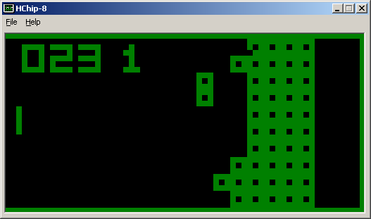
should eventually be executed in our emulator and display something like this on the screen:

With the end done, go to a little tedious, but necessary theory.
So, what is the CHIP-8 gaming platform? Those who speak English can read a detailed article on Wikipedia , but I will try to retell the main points in my own words.
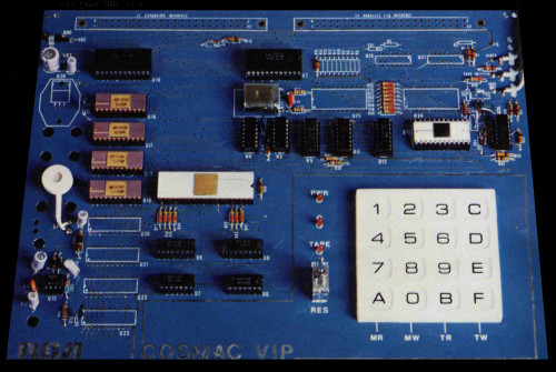
CHIP-8 is an interpreted programming language created in the mid-70s for the COSMAC VIP and Telmac 1800 gaming consoles. Programs written and compiled for CHIP-8 are executed on the prefixes themselves in virtual machines. Well, by modern analogy, this is something like Java bytecode. I generally advise you to forget at the time of creating the emulator that this is an interpreted language, and assume that we are emulating an iron platform - a kind of processor with its own instruction set. Further, when I say “prefix”, I will mean CHIP-8.
Our console has a memory, a processor, a video output device, sound, and of course an input device. Consider all the components in more detail:
Memory
The prefix has 4Kb of main memory (RAM). The memory starts at offset 200h and ends at offset FFFh, respectively. Why does program memory start at offset 200h? It's very simple - the first 512 bytes of memory in the original consoles are taken by the interpreter of the CHIP-8 language in the machine codes of the processor on which the prefix is built.
Registers
In CHIP-8, there are sixteen 8-bit data registers with the names V0 ... VF. Register VF is responsible for the carry flag (carry flag) for the operations of addition / subtraction. Also in the console there is a 16-bit address register I.
Stack
The stack is used to store the return address when the routine ends. The original version of the console has a stack size of 48 bytes, which corresponds to twelve nesting levels of subroutines. Since we are not limited in resources, we will use 16 levels of investment. This is what most CHIP-8 emulators do.
Timers
In the console there are two 8-bit timers, they both decrease with a frequency of 60 Hz, until it reaches zero.
Delay timer: This timer is used for various delays in games, its value can be read / changed using commands.
Sound timer: When the timer value is non-zero, a squeaking sound is output.
Input device
Input is carried out using 16 keys. In the original console, the keys have codes from 0h to Fh. If we emulate on a computer, it is best to use the right NumPad part of the keyboard, the one where the numbers 0-9 and NumLock are located. The keys '8', '4', '6', and '2' are commonly used to move, although not always the case. It depends on the game.
Graphics and sound
In our console, the screen resolution is 64x32 pixels, one color (monochrome). The output is implemented using sprites, which are always 8 pixels wide and can be from 1 to 15 pixels long. If while drawing the sprite is superimposed on another sprite, then at the overlap point the color is inverted, and the VF (carry flag) register takes the value 1. Otherwise it takes the value 0.
As noted above, a nasty squeaky sound is played, if the Sound timer value is non-zero. I think we will not implement the sound at all, I do not like these beeps.
Teams
Our processor (CHIP-8 in fact) has exactly 35 instructions, each command is always two bytes long. Here the table of commands will not be reprinted, it is in Wikipedia . You can take a few examples from there, for example:
00E0 Clears the screen. - when we meet in code 00E0, just clear the screen.
6XNN Sets VX to NN. - set the VX register to NN. For example, if you meet the command 635A, then you need to write the value 5Ah to the V3 register.
From the above, it can be seen that this platform is the best way to start learning how emulators work. Here we have no clever masked and non-masked interrupts, no heaps of peripherals with I / O ports, no complicated timers, and so on. Know, read to yourself commands by two bytes from the file, compare them with opcodes and execute what is required. And the teams then just nothing - 35 pieces. There are pitfalls, and where without them? Well, let's get started. And we begin perhaps with memory.
It is clear that the first thing when we start the emulator, we need to initialize our virtual machine. That is, clear the memory, stack, registers and video memory. As I wrote above, the offset by which we will load our emulated program is 200h. Prior to this, that is, from offset 000h to 1FFh, there must be an original interpreter. It has, among other things, a small font that starts at offset 000h and goes up to 050h and occupies 80 bytes. It can be seen in the source code of my emulator. Yes, I apologize for myFrench Delphi, but I am programming on it, do not blame me. For simplicity, I created this structure:
So, at the beginning we fill all arrays with zeros, then copy the font (Font: array [1..80] of byte) into the Memory array starting from zero and initialize all values:
Now everything is ready, you can read the emulated program into memory at offset 200h and take on the interpretation of codes. Here we will have to remember a little bit who the bits are and how to extract them from bytes and words (word). For simplicity, I created the procedure ExecuteOpcode (opcode: word), to which an opcode of two bytes is transmitted, interpreted and executed. To understand the meaning, you can check with the table of commands from Wikipedia .
And so on, I think the idea should be more or less clear. At the time of writing the interpreter, you can use stubs for some commands. Now, when we implement the main processor commands, it remains to draw a conclusion to the screen and implement the input device. The DXYN command is responsible for displaying on the screen. In the VX register is the X coordinate, in the VY register is the Y coordinate from which we need to start drawing the sprite. The address register I at this time points to the bitmap of the sprite. I will not make the implementation of drawing graphics, I think there should be no difficulties, especially since you can always look at the source at the end of this post. The same with the keyboard.
Of course, I could not mention all the implementation details in this article. The goal is to just push a thought and show an analysis of opcodes. If anyone is interested, you can see my implementation of the emulator on Delphi, or find other implementations of emulators on the Internet. How fashionable to say, thousands of them. Starting from Visual Basic and ending with iron solutions.
I apologize in advance for my code, I did not put it in order - I poured it as it is. The main interesting file there is hchip.pas, it implements all the emulation.
There is also a good English-speaking forum EmuTalk, which specifically highlights the branch dedicated to Chip-8 emulation.
A page on which you can download probably one of the best chip8 emulators and games for it.
Anyway, on request in google "chip-8" you can find everything you need.
What else can you do? You can slightly modify our emulator to support Super chip-8 instructions and sprites. Yes, a lot more that you can.
Have a nice day everyone.
In this post I would like to talk about creating a simple emulator of the gaming platform CHIP-8 from the distant 70s. Firstly, we touch the history, and secondly, this platform, due to its simplicity, will allow creating a fully functional emulator even for novice programmers.
')
the end
As if this was not strange, but I'll start from the end. Here is a program
OPTION BINARY ; We want a binary file, not an HP48 one.
ALIGN OFF ; And we don’t want auto alignement, as some
; data can be made of bytes instead of words.
LD V0 , 0
LD V1 , 0
LOOP :
LD I , LEFT ; We draw a line
; is 0 or 1. If we suppose that it will be 1, we keep
; drawing the left line. If it is 0, we change register
; I to draw a right line.
RND V2,1 ; Load in V2 a 0 ... 1 random number
SE V2 , 1 ; It is 1? If yes, I still refers to the left line
; bitmap
LD I , RIGHT ; If not, we need it
; bitmap
DRW V0 , V1 , 4 ; And we draw the bitmap at V0, V1.
ADD V0,4 ; The next bitmap is 4 pixels right. So we update
; V0 to do so.
SE V0 , 64 ; If V0 == 64, we
; skip the jump to LOOP, as we have to update V1 too.
JP LOOP ; We did not draw a complete line? So we continue!
LD V0 , 0 ; The first bitmap of each line is located 0, V1.
ADD V1,4 ; We update V1. The next line is located 4 pixels doan.
SE V1 , 32 ; Have we drawn all the lines? If yes, V1 == 32.
JP LOOP ; No? So we continue!
FIN : JP FIN ; Infinite loop ...
RIGHT:; 4 * 4 bitmap of the left line
DB $ 1 .......
DB $ . 1 ......
DB $ .. 1 .....
DB $ ... 1 ....
LEFT:; 4 * 4 bitmap of the right line
; And YES, it is like that ...
DB $ .. 1 .....
DB $ . 1 ......
DB $ 1 .......
DB $ ... 1 ....
occupying 38 bytes and in compiled form it looks like this
should eventually be executed in our emulator and display something like this on the screen:
With the end done, go to a little tedious, but necessary theory.
Architecture
So, what is the CHIP-8 gaming platform? Those who speak English can read a detailed article on Wikipedia , but I will try to retell the main points in my own words.
CHIP-8 is an interpreted programming language created in the mid-70s for the COSMAC VIP and Telmac 1800 gaming consoles. Programs written and compiled for CHIP-8 are executed on the prefixes themselves in virtual machines. Well, by modern analogy, this is something like Java bytecode. I generally advise you to forget at the time of creating the emulator that this is an interpreted language, and assume that we are emulating an iron platform - a kind of processor with its own instruction set. Further, when I say “prefix”, I will mean CHIP-8.
Our console has a memory, a processor, a video output device, sound, and of course an input device. Consider all the components in more detail:
Memory
The prefix has 4Kb of main memory (RAM). The memory starts at offset 200h and ends at offset FFFh, respectively. Why does program memory start at offset 200h? It's very simple - the first 512 bytes of memory in the original consoles are taken by the interpreter of the CHIP-8 language in the machine codes of the processor on which the prefix is built.
Registers
In CHIP-8, there are sixteen 8-bit data registers with the names V0 ... VF. Register VF is responsible for the carry flag (carry flag) for the operations of addition / subtraction. Also in the console there is a 16-bit address register I.
Stack
The stack is used to store the return address when the routine ends. The original version of the console has a stack size of 48 bytes, which corresponds to twelve nesting levels of subroutines. Since we are not limited in resources, we will use 16 levels of investment. This is what most CHIP-8 emulators do.
Timers
In the console there are two 8-bit timers, they both decrease with a frequency of 60 Hz, until it reaches zero.
Delay timer: This timer is used for various delays in games, its value can be read / changed using commands.
Sound timer: When the timer value is non-zero, a squeaking sound is output.
Input device
Input is carried out using 16 keys. In the original console, the keys have codes from 0h to Fh. If we emulate on a computer, it is best to use the right NumPad part of the keyboard, the one where the numbers 0-9 and NumLock are located. The keys '8', '4', '6', and '2' are commonly used to move, although not always the case. It depends on the game.
Graphics and sound
In our console, the screen resolution is 64x32 pixels, one color (monochrome). The output is implemented using sprites, which are always 8 pixels wide and can be from 1 to 15 pixels long. If while drawing the sprite is superimposed on another sprite, then at the overlap point the color is inverted, and the VF (carry flag) register takes the value 1. Otherwise it takes the value 0.
As noted above, a nasty squeaky sound is played, if the Sound timer value is non-zero. I think we will not implement the sound at all, I do not like these beeps.
Teams
Our processor (CHIP-8 in fact) has exactly 35 instructions, each command is always two bytes long. Here the table of commands will not be reprinted, it is in Wikipedia . You can take a few examples from there, for example:
00E0 Clears the screen. - when we meet in code 00E0, just clear the screen.
6XNN Sets VX to NN. - set the VX register to NN. For example, if you meet the command 635A, then you need to write the value 5Ah to the V3 register.
Practice
From the above, it can be seen that this platform is the best way to start learning how emulators work. Here we have no clever masked and non-masked interrupts, no heaps of peripherals with I / O ports, no complicated timers, and so on. Know, read to yourself commands by two bytes from the file, compare them with opcodes and execute what is required. And the teams then just nothing - 35 pieces. There are pitfalls, and where without them? Well, let's get started. And we begin perhaps with memory.
It is clear that the first thing when we start the emulator, we need to initialize our virtual machine. That is, clear the memory, stack, registers and video memory. As I wrote above, the offset by which we will load our emulated program is 200h. Prior to this, that is, from offset 000h to 1FFh, there must be an original interpreter. It has, among other things, a small font that starts at offset 000h and goes up to 050h and occupies 80 bytes. It can be seen in the source code of my emulator. Yes, I apologize for my
Display : Array [ 0..64 * 32-1 ] of Byte ; // video memory
Memory : Array [ 0..4095 ] of Byte ; // RAM memory
Stack : Array [ 0..15 ] of Word ; // stack
Registers : Array [ 0..15 ] of Byte ; // registers
rI : Word = $ 200 ; // I register
SP : Byte = 0 ; // stack counter
PC : Word = $ 200 ; // mem offset counter
delay_timer : Byte = 255 ; // delay timer;
sound_timer : Byte = 255 ; // sound timer;
So, at the beginning we fill all arrays with zeros, then copy the font (Font: array [1..80] of byte) into the Memory array starting from zero and initialize all values:
FillChar ( Memory , 4096 , 0 ) ; // clear the main memory
Move ( Font , Memory , 80 ) ; // copy the font into it at offset 000h
FillChar ( Stack , 16 , 0 ) ; // clear the stack
FillChar ( Registers , 16 , 0 ) ; // reset registers to zero
rI : = $ 200 ; // address register I at the beginning of the program
PC : = $ 200 ; // array offset
SP : = 0 ; // stack counter
delay_timer : = 0 ; // timers to zeros
sound_timer : = 0 ;
Now everything is ready, you can read the emulated program into memory at offset 200h and take on the interpretation of codes. Here we will have to remember a little bit who the bits are and how to extract them from bytes and words (word). For simplicity, I created the procedure ExecuteOpcode (opcode: word), to which an opcode of two bytes is transmitted, interpreted and executed. To understand the meaning, you can check with the table of commands from Wikipedia .
Procedure ExecuteOpcode ( opcode : word ) ;
Begin
case ( op_code and $ F000 ) shr 12 of // select the first 4 bits from the opcode
$ 00 : Begin // opcode started from scratch
Case op_code and $ 00FF of
// This is our opcode 00E0 - cleaning the screen
$ E0 : Begin
// We do things, that is, we stupidly clear the screen
exit;
End ;
// And this is - 00EE - exit from the procedure
$ EE : Begin
// Restore the address from the stack, jump to it
exit;
End ;
End ;
// And here we get, if the opcode started from scratch, but neither E0 nor EE ended
// Therefore, either we crash or display the message Invalid Opcode
exit;
End ; // end check for zero opcode
$ 01 : Begin // the first four bits of the opcode is 1 (the opcode began with one)
// This is JMP, jump. Jump to the desired address
PC : = op_code and $ 0FFF;
exit;
End ;
$ 02 : Begin // the first four bits of the opcode are 2 (the opcode began with a two)
// Call the subroutine.
// increment the stack pointer
// put the current address on the stack
// and pry on the subroutine
End ;
//
// This continues to the opcode, which begins with 7.
//
$ 08 : Begin // opcode started from 8. Here you need to look at the last 4 bits
case op_code and $ 000F of // last 4 bits of opcode
// mov vx, vy
$ 00 : Begin
// Enter the VY value in the VX register
exit;
End ;
// or vx, vy
$ 01 : Begin
// VX = VX or VY
exit;
End ;
//
// this goes on to 0E
//
End ; // end of checking the last 4 bits of the opcode
// get here if Invalid Opcode
exit;
End ; // end of test if opcode started at 8
And so on, I think the idea should be more or less clear. At the time of writing the interpreter, you can use stubs for some commands. Now, when we implement the main processor commands, it remains to draw a conclusion to the screen and implement the input device. The DXYN command is responsible for displaying on the screen. In the VX register is the X coordinate, in the VY register is the Y coordinate from which we need to start drawing the sprite. The address register I at this time points to the bitmap of the sprite. I will not make the implementation of drawing graphics, I think there should be no difficulties, especially since you can always look at the source at the end of this post. The same with the keyboard.
Conclusion
Of course, I could not mention all the implementation details in this article. The goal is to just push a thought and show an analysis of opcodes. If anyone is interested, you can see my implementation of the emulator on Delphi, or find other implementations of emulators on the Internet. How fashionable to say, thousands of them. Starting from Visual Basic and ending with iron solutions.
I apologize in advance for my code, I did not put it in order - I poured it as it is. The main interesting file there is hchip.pas, it implements all the emulation.
There is also a good English-speaking forum EmuTalk, which specifically highlights the branch dedicated to Chip-8 emulation.
A page on which you can download probably one of the best chip8 emulators and games for it.
Anyway, on request in google "chip-8" you can find everything you need.
What else can you do? You can slightly modify our emulator to support Super chip-8 instructions and sprites. Yes, a lot more that you can.
Have a nice day everyone.
Source: https://habr.com/ru/post/100907/
All Articles